Project start: April 2013
Record Lathe - Mechanics
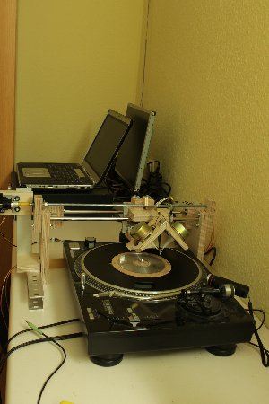
After the first tests with the prototype went well the next to improve on was the mechanics to move the cutterhead.
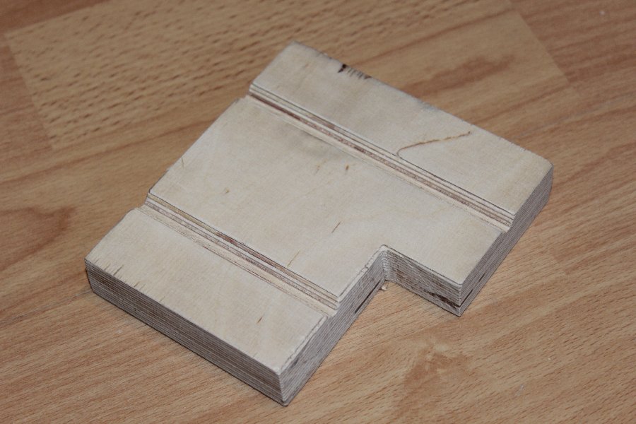
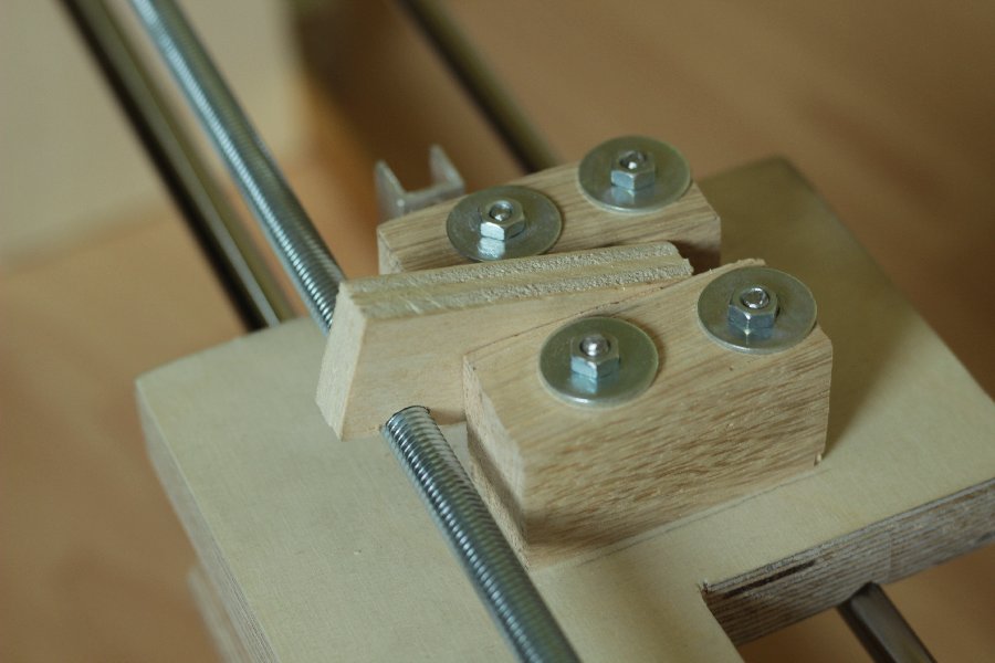
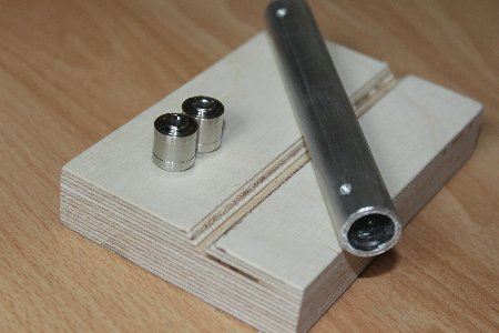
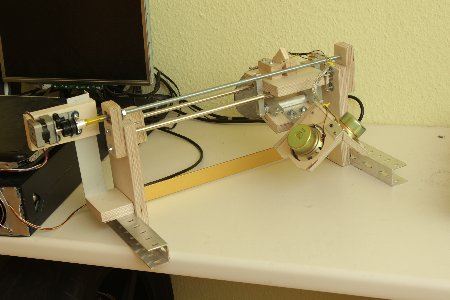
The base structure was build quickly. A carriage is going to slide back and forth on the two steel rods (out of an old scanner).
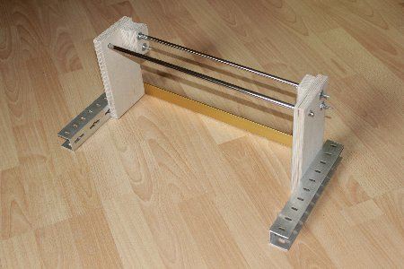
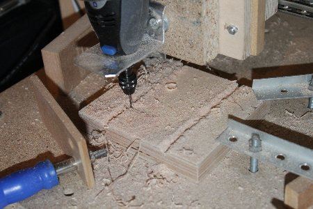
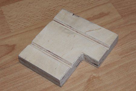
The carriage is made out of a 20mm thick multiplex wood piece in which two parallel grooves are milled.
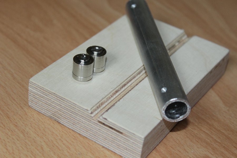
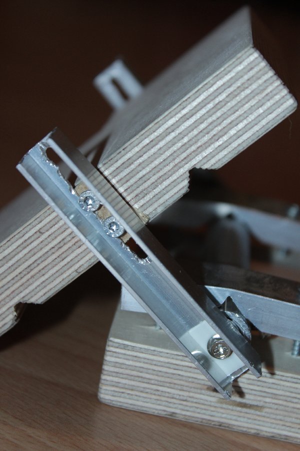
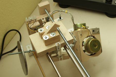
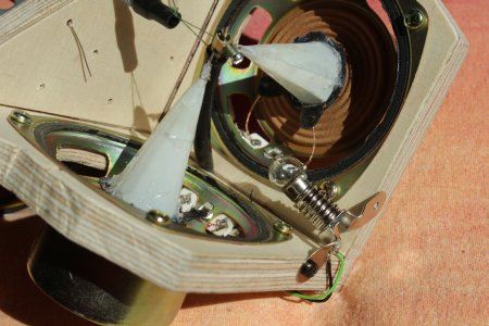
Now the cutterhead (which I am going to keep from the prototype) has to be mounted in such a way that it can rotate up and down.
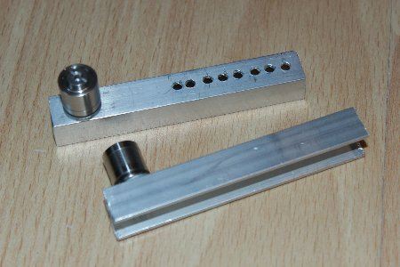
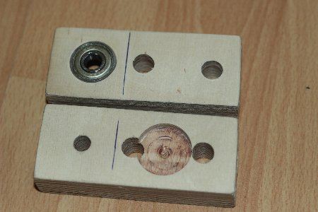
For this I am using two ball bearings out of two broken hard drives (the bearing for the read write head assembly). The bearings are pressed in a piece of aluminium tube and hold in place by a small PC case type screw from the side.
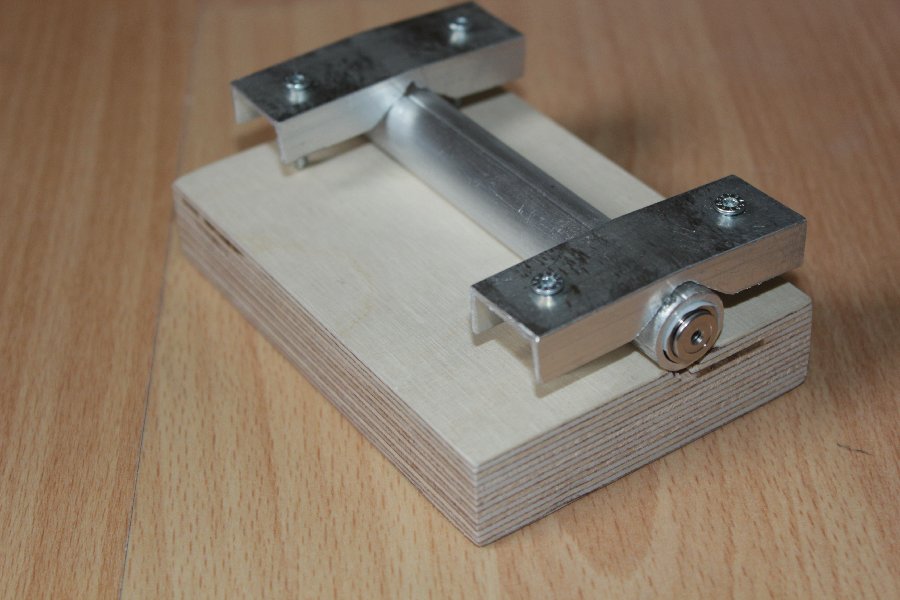
The tube rests in another groove on a piece of wood to make shure it stays absolutely parallel. To keep everything together a piece of aluminium profile is placed and screwed down from above on each side.

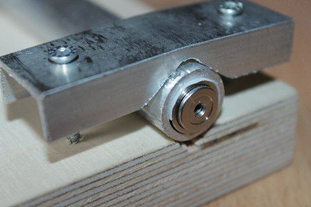
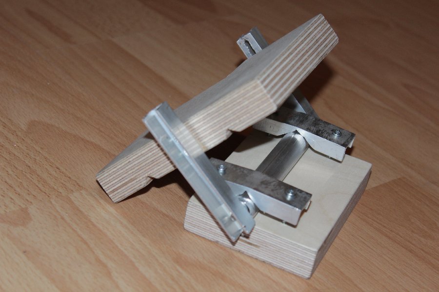
The ball bearings are then screwed to a U-profile, such that wood piece can be attached to the carriage. Also the height can be adjusted later by losening the screws and sliding it up or down.


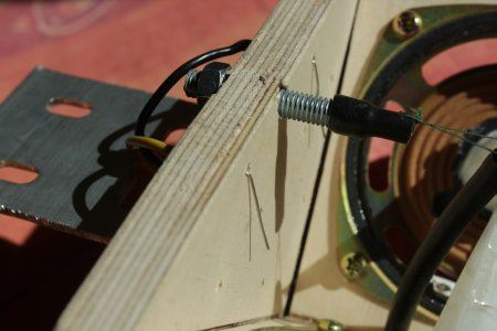
On the rear side a M6 threaded rod is screwed in, to attach a counterweight of ca. 500 gramms to its end.

Besides I changed the needle holder of the cutterhead by making the thread adjustable by a thread screw.
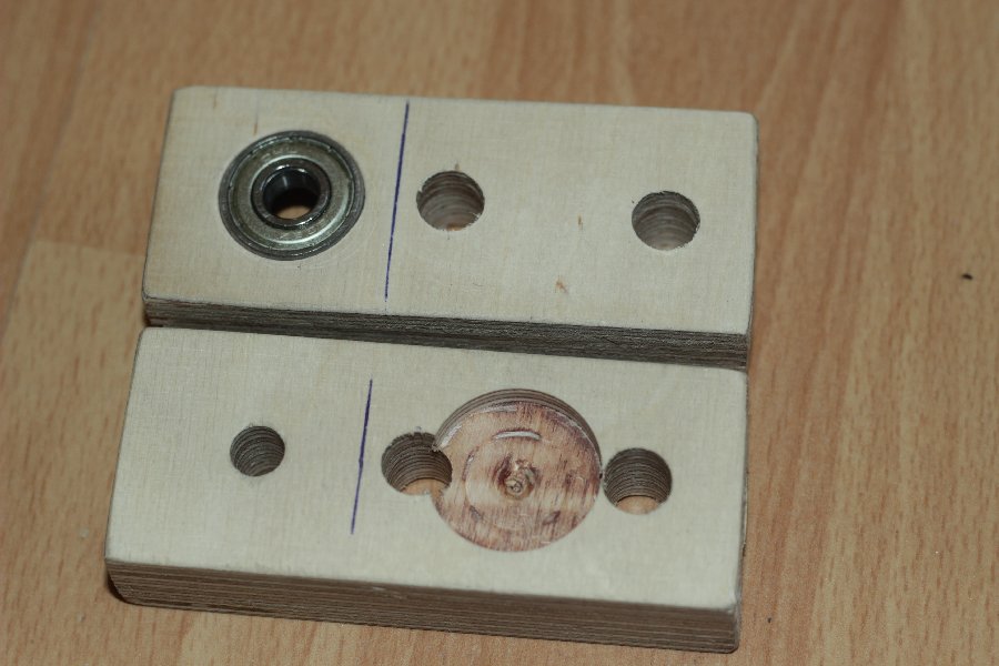
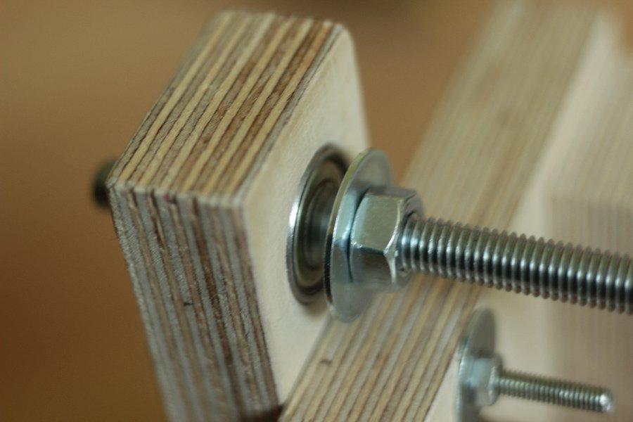
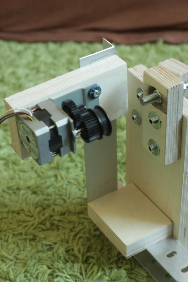
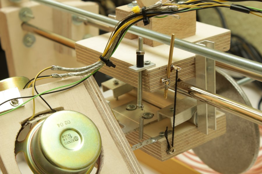
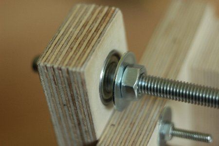
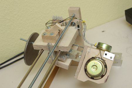
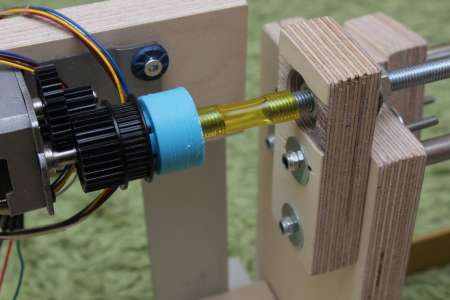
Back to the mechanics: This time the M8 threaded rod is placed above the carriage. On both sides a small wood piece is mounted in which the rod sits. On one side I flush-mounted a ball bearing. The threaded rod is then fixed to the bearing by screwing nuts from each side to it with a small piece of rubber tube to remain some backlash.
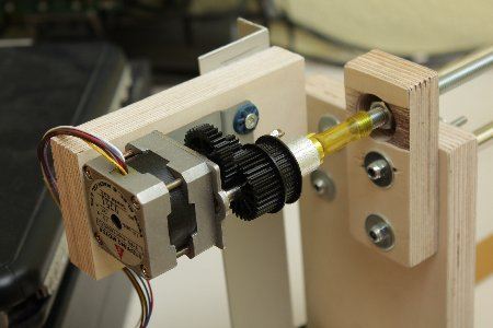
A stepper motor is mounted behind the ball bearing. This motor rotates the threaded rod through a rubber tube. The tube is there to keep vibrations of the stepper motor away from the cutterhead. Also the motor is not directly attached to the rest of the assembly. Because the threaded rod may not be perfectly parallel to the movement of the carriage the wood piece is not directly attached to the carriage but is just kept in place by two wood blocks on either side. The backlash is negligible because the feed only needs to be exact in one direction during cutting. Because the thread is not enclosed, the wood piece on top can just be lifted to move the carriage by hand.
The carriage now needs to move if the threaded rod is rotating, therefore I attached a piece of wood to the carriage which rides on the threads. I used wood to reduce grinding noises .


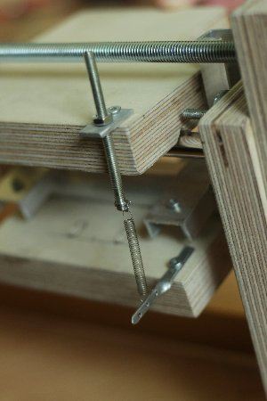
The cutting weight can be adjusted by moving the counter weight. Because this is just a coarse adjustment a small spring is attached to the front part. By moving the small thread screw up the spring is stretched and removes weight from the cutterhead.
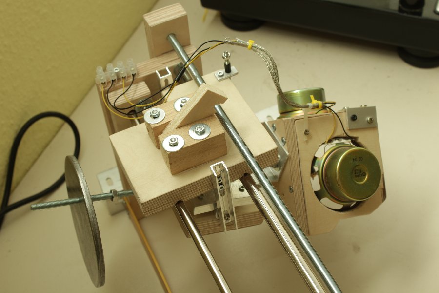
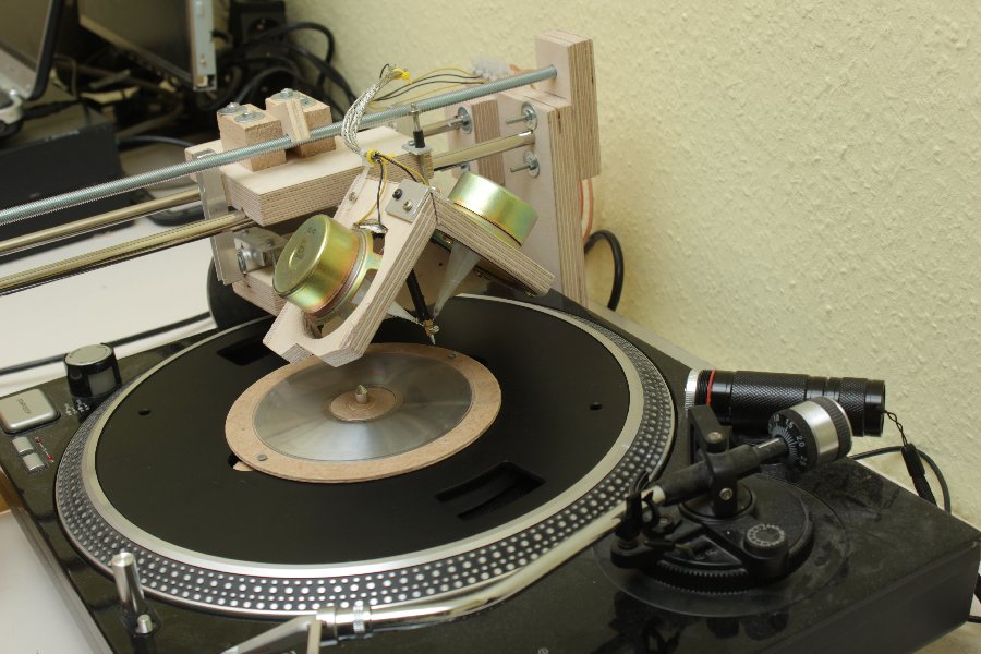
So far so good. Here you can see the counterweight, a 530 gramm heavy metal disc.
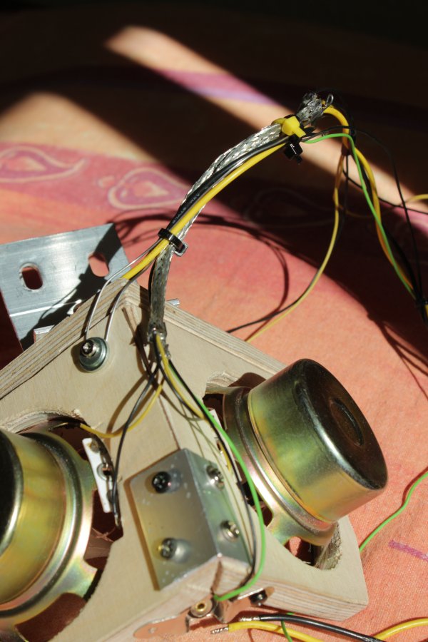
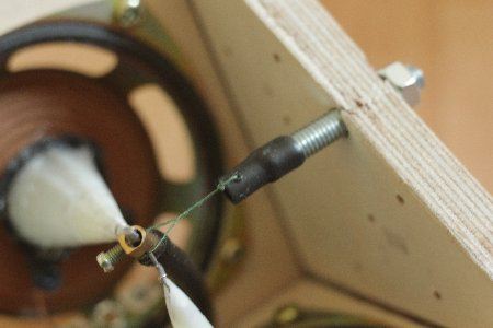
The wires for the speakers are, together with a rigid piece of wire, threaded trough a piece of wire shielding. This enables me to bend the wires up in a way that they don't touch the threaded rod.
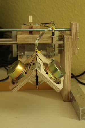
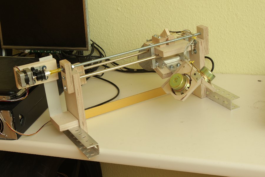
The turntable can simple be placed under the cutterhead. The new assembly now made it possible to reduce the groove spacing during cutting without them accidentally getting too close and possibly touching.

The first "cut" with this machine went supprisingly well. Sadly the result is still a bit too quiet.
Some news on the cutterhead part: A small 3W light bulb is now illuminating the needle, which also gives a warm, analog feeling.
Also two wires are now preventively put though the backplanel to later maybe attach a needle heater.
A thicker bundle of wires now leads out of the cutterhead. A more rigid wire, mounted to the carriage, is now keeping the wires away from the threaded rod.

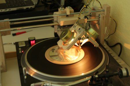
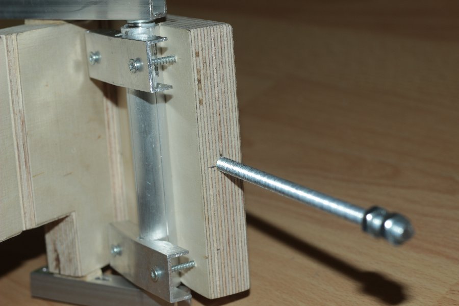
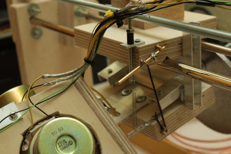
A small lever is also now mounted to the carriage in order to lower or raise the cutterhead.
Though a small thread the cutterhead can now be lifted. The lever then latches in the up position because of the weight of the cutterhead. Other than in the picture the thead will not be tight when the cutterhead is lowered because it will rather sit on the surface of the material to record on.


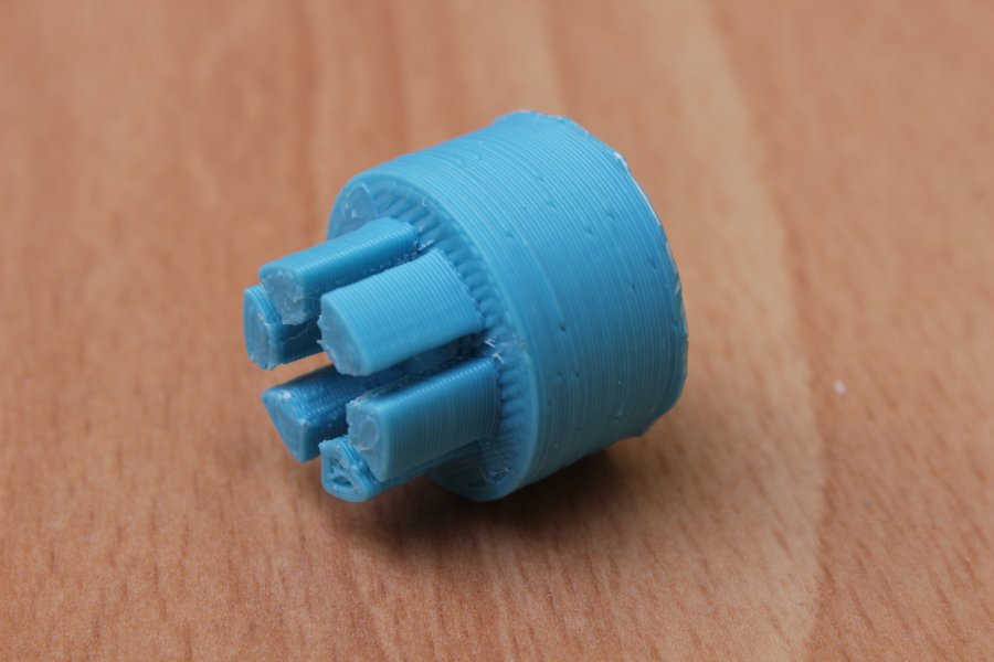
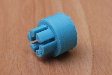
In the meantime I impoved the connection from the stepper motor to the threaded rod. The 3d-printed part is now loosely put on the inner part of the gears and can be easily removed.
The next thing to improve on further was the cutterhead. The cheap pc speakers were not meant to be a permanent solution. So a
new cutterhead had to be build.
 Prototyp