Project start: November 2017
Last updated: July 2023
E-Bobby Car Controller (Teensy)
2019 I build a STM32 Bluepill Microcontroller into the bobby car as a way of centralized motor control.
Controling the hoverboard mainboards via USART was very easy thanks to the multiple hardware USART ports of the STM32F103C.
If my mind serves me correclty I had some minor bugs and issues which lead me to use a Teensy 3.2 in the end.
Programming is done directly via USB. Hard- and software seemed to me a bit more sophisticated, .. this was enough pro arguments for me.
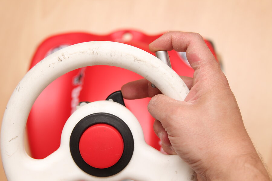
In the meantime the analog shoulder button from an X-Box controller was used again, but this time for the brake.
Using my index finger for the throttle and the middle finger on the brake lever was very usable for me.
This way the left hand is still kept free to carry stuff or to spontaneously grab tighter on the steering wheel.


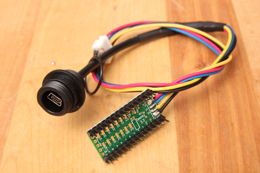
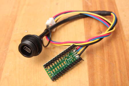
As mentioned the Teensy is pretty simple and fast programmed via USB.
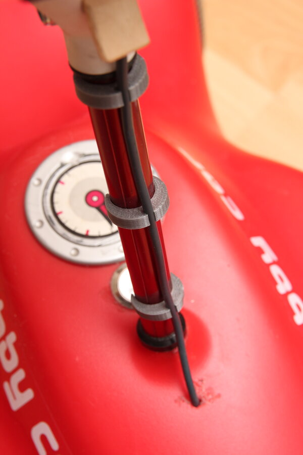
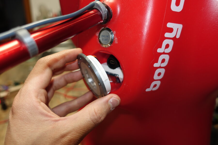
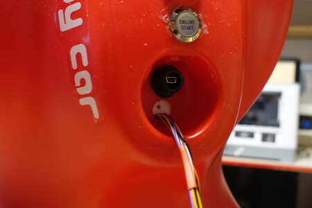
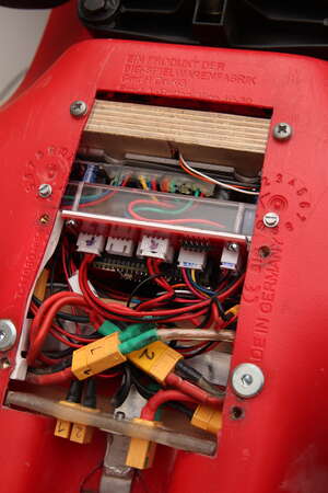
For faster access a
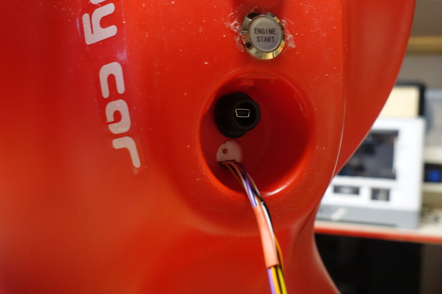
Mini USB Connector is build into the fuel tank cap.
The "Engine Start" button is now also hot glued in place. Vibrations during driving unscrew pretty much every nut.
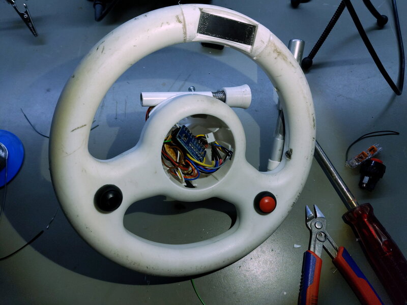
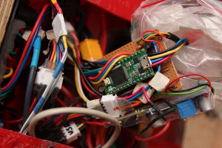
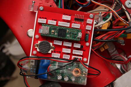
This is the new heart of the bobbycar, a Teens 3.2.
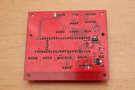
First I thought about etching a PCB to neatly route every connection.
But especially here I except a lot of changes to be made in the future. Also these are nearly all direct connections from the connectors to the microcontroller.
Most of the circuit diagram of the
Bobby Car Controller is still valid.
For space, usability and safety reasons I abandoned the use of the relais-hoverboard-turn-on part.
Startup now includes plugging in the XT90 antispark, turning on the teensy with the "Engine Start" button followed by pressing both hoverboard power buttons.
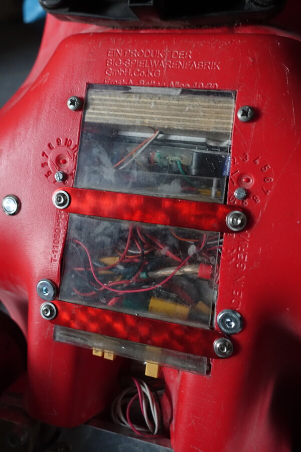
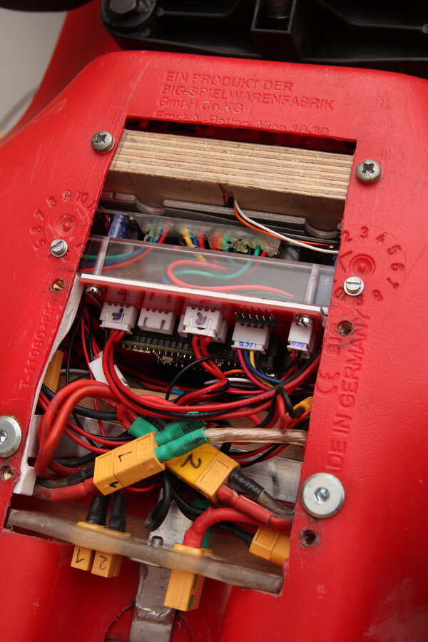
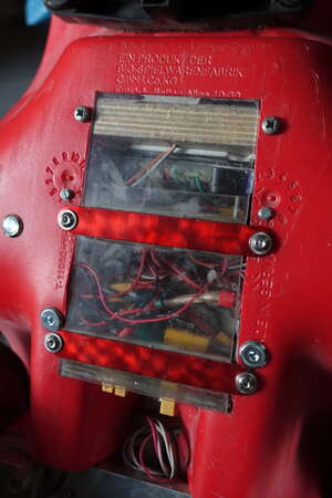
This perfboard sits then, isolated by a plastic bag against short circuits, inside the bobbycar surrounded by a mess of wires.
After some more intese test driving the hole for the steering rod had been opened somewhat.
I used this opportunity to turn a bushing out of POM to fit in the further drilled opening.
A short piece of rubber tubing at the lower end of the steering rod decreased the play quite a lot.
After using a healthy amount of grease at the sliding and rubbing parts of the steering mechanism the repair was finished.
Before the cable coming from the steering wheel was held in place by zip ties, now 3D printed cableclips can be found in their place.


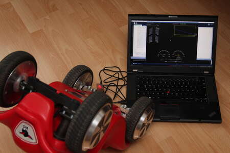
I was able to wire out a spare hardware serial port for live-debugging output.
Over this I print out debugging values as csv format with variable rates up to 50 Hz.
A hacked together piece of Processing software is used to visualize all of it.
I would liked to use wireless data transmission, but the HC-12 866 MHz modules didn't gave me sufficient range with only 2m.
This had likely something to do with the bad positioning of the antennas at the very rear of the bobby car.
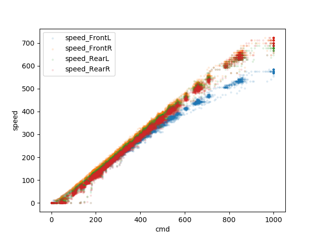
Here I plotted the commanded value "cmd" which is sent to the motor controllers (on the x axis) in relation to the resulting freewheeling rotational speed of the four motors.
Here my assumption got confirmed that the front left motor doesn't turn as fast as the others.
What I saw as a lower rpm in this freewheeling test showed itself as recuperation during driving at this wheel.
While three wheels consume current to accelerate the vehicle one wheel puts some of that energy back into the battery.
Sadly I did not achieve to build a perpetuum mobile. Rather I felt the steering always to pull a bit to the left.
Indeed the culprit looked a bit different regarding the tire profile, compared to the others. If this is really an indication I can't say for sure.
After a wheel swap the motor was still not as fast as the others, but recuperation during acceleration was fixed.
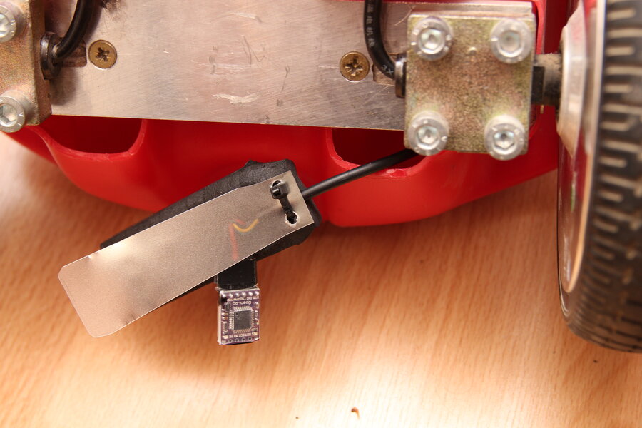
If live logging does't work at least I can record these values.
For this a
Sparkfun OpenLog was connected.
It records data into a TXT file.
Starting the teensy first prints out the header for the csv. Then the data follows for every row.
With this the resulting file can be directly read or analyzed.


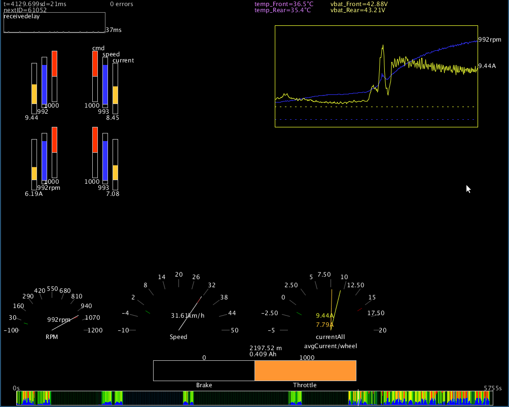
Here a screenshot, how visualization of a logfile looks like.
The colorful timeline at the bottom serves as an overview. Throttle, brake and current are used to determine the color.

Meanwhile I went away from using torque mode at the hoveraboardcontroller in favor of sinusoidal motor control.
The reason for this was that driving didn't felt as "direct" as it did without.
For torque mode a current control is implemented inside the STM of the hoverboard PCB.
With this mode enabled acceleration feels generally more natural, because throttle controls the power of the motors.
On of the very early versions of the hoverboard-firmware-hack implemented either communation or sinusoidal mode, where by releasing the throttle the motors did freewheel.
As far as I understand this was not a feature but a bug.
In all the current versions these simpler control modes brake very strongly when releasing the throttle.
If I would use the throttle without further filtering/processing it would quickly result in a bent steering rod.
A compromise between direct sinusoidal control and current control would be nice.
This I implemented at the teensy side. The hoverboard boards are still just used as ESCs.
The idea was to use the throttle value during acceleration (new poti value > old poti value).
As soon as the throttle is lower than the current commanded value to the motor controlers, the speed should be reduces slowly to "simulate" freewheeling.
This "simulated freewheeling by constantly reducing speed" pushed me unerringly into the wall. Braking with my feet was ignored completely.
Information about these external braking forces can be obtained by looking at the motor current. As soon as the current increases the sent value should be reduced faster.
Both of these ideas were implemented. Mainly to make sure that if for some reason current can't be measured acurately or sent to the teensy braking is still possible.
Because therese now a braking lever available it's position is used to scale these calculations proportionally.
Now slow-paced and not so slow-paced driving was again possible. Freewheeling was working perfectly, only braking was mostly very abrupt.
Lowering the parameters for braking resulted at the same time in a longer braking distance when trying to emergency brake.
I reckon the cause to be the delay between hitting the brake until the motors finally slow down enough to feel it.
A solution could be to allow the current control to raise the speed values. This however would lead to an implementation of full current control like it would be with torque mode.
The principle of "ducking", as known from music production, helped me in this case.
Applied to the bobby car this means further lowering the speed value when pushing the brake lever, but only temporarily. Releasing the brake restores some amout of the speed value.
Initial braking is not changed really, but the motors do not slow down as much as before when releasing the brake early.
Lastly I applied an exponential curve to the brake position and it now drives better than ever.
10 Ah Battery
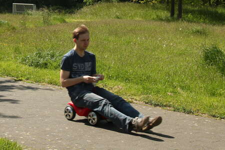
Since the bobbycar is now working again I took it out a few times for a ride.
The values for maximum current and thus power shouldn't be too different from what I had a few years earlier.
But the controllers were starting to beep very early because of low voltage when going faster even though the battery had just been charged up.
Looking at the log files the voltage starts at around 49V (4.1V/cell * 12 cells) but drops below 42V during acceleration.
It was possible to drive a good amount of time this way but since I used old hoverboard 18650 cells it was time for a new battery pack.
I really wanted to go cheap and rip apart an e-bike battery or something but haven't had any at hand.
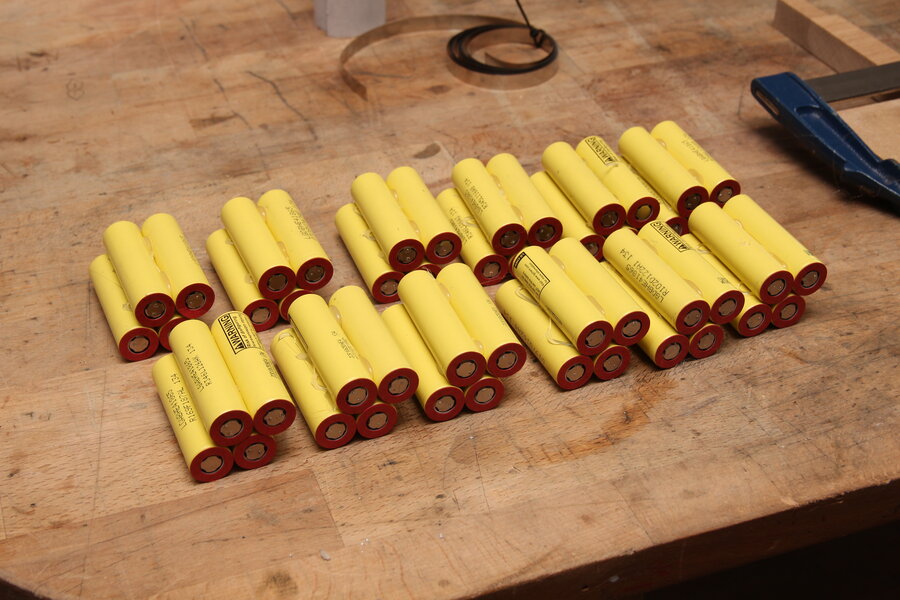
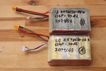
Looking forward to a fun summer I bit the bullet and bought a bunch of refurbished LG ICR18650-HE4 2500mAh cells from
nkon.nl.
To have a drop in replacement I again went for two packs of 6S4P which sums up to 48 individual cells costing almost 200 €. Thats more than the whole bobbycar so far I think, Ouch!
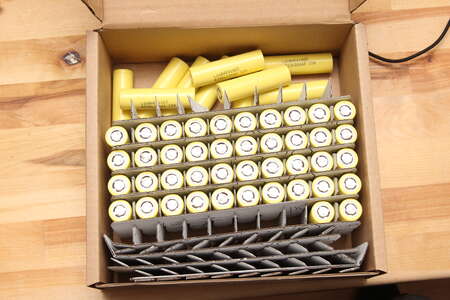

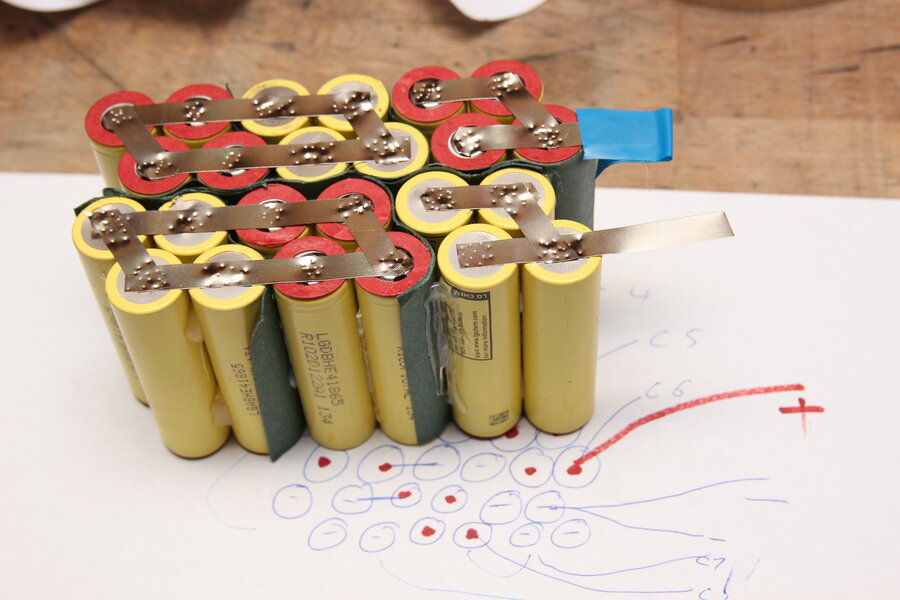
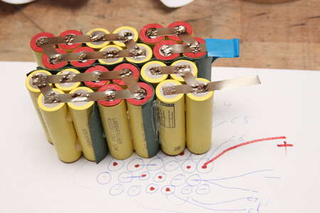
Placement and routing is the same as the first battery pack.
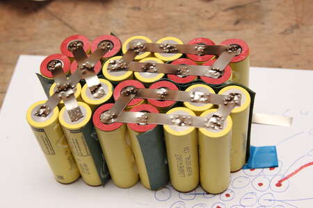
This time I added some protective sheets betweend the cells that have not the same voltage potential on their metal casing.
Also covering the finished spot-welds when placing a new nickel strip is a good advice. Shorting the wrong things really can end in a nasty fire.
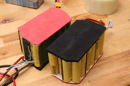
I added some foam to protect the solder connections and surrounded everything with tape.
This battery pack has now twice the capacity as the last one and is theoretically capable of delivering 80 Amps (4P * 20A). The bobbycar is software limited to 2*15A = 30A.
A quick driving test showed that with the voltage staying at 47V at full throttle the maximum speed was 38 km/h instead of 32 km/h. Not that speed increase was my goal in the first place.
Controller PCB
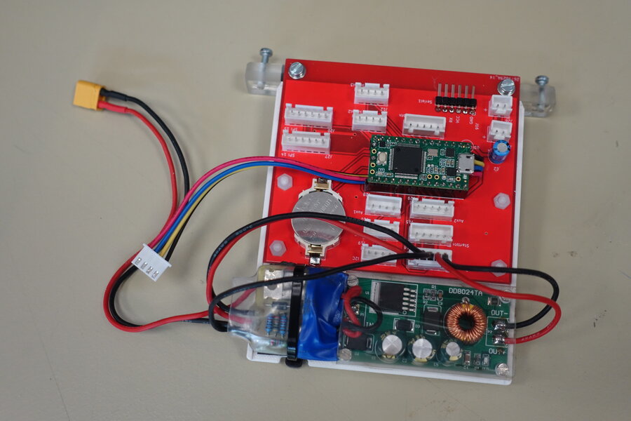
On the MCH2022 the 5V stepdown for the Teensy supply voltage broke.
Later I replaced it by a DD8024TA, which should tolerate up to 80V input voltage, because I suspected a voltage spike as the cause.
Overall, I was more and more bothered by the messiness of the many cables and possibility of cable breaks at the solder connections to the board.
When I pulled the Teensy out of the belly of the Bobbycar, the first cable broke off immediately.
In the meantime I had the feeling that the setup with the Teensy 3.2 and the used periphery works well and can be set up a bit more permanent and safe.
I had already created a wiring diagram. I just had to update it a bit and remove some components from the PCB.
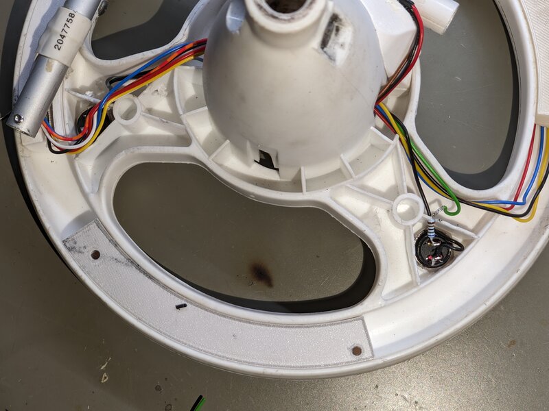
Instead of the internal ADC of the Teensy I will use an ADS1115 I2C 4-channel A/D converter to read throttle and brake position at the steering wheel.
Since I need a few more inputs at the steering wheel in the future (not least because of the planned redundant sensors) the A/D converter will be installed in the steering wheel under the horn.
The four-wire cable going there will carry I2C signals from now on.
 20230614_Bobbycar_wiring.pdf
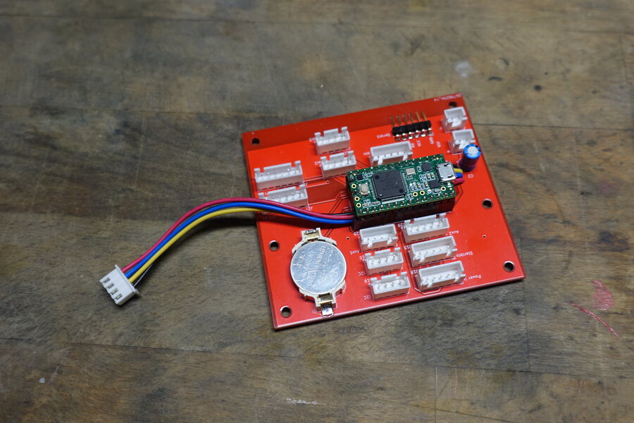
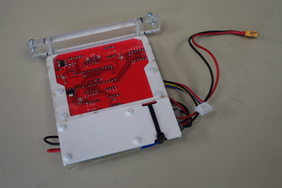
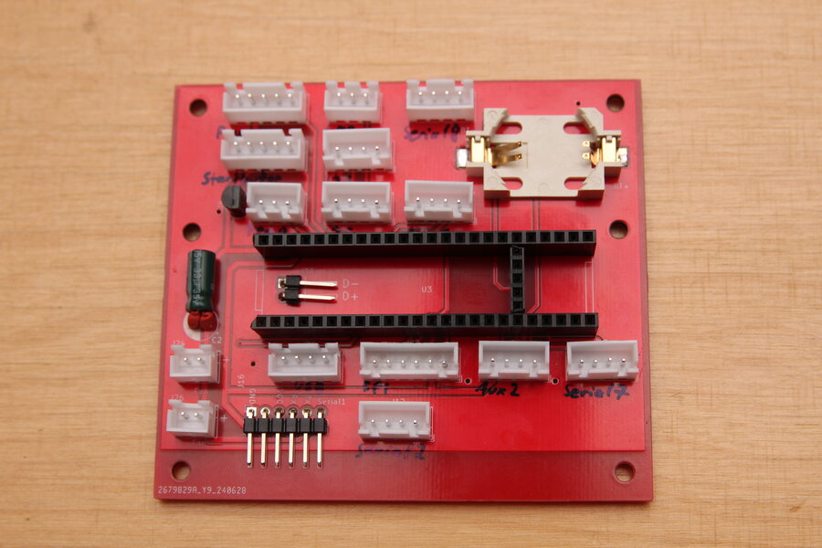
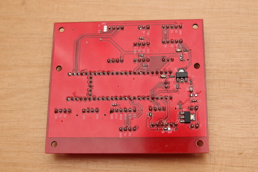
With the schematic it was easy to puzzle together a PCB.
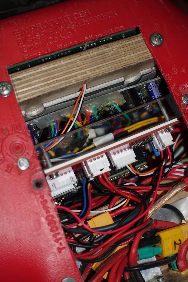
The biggest difference to the perfboard is the use of JST-XH connectors. The sockets are crimped to the cables, which makes them much more robust against breakage.
Also, it bothered me for a long time that the board only dangled loosely and was not fixed in place.
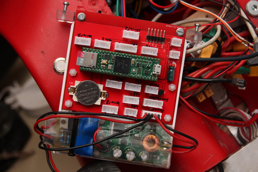
Together with stepdown and latch circuit, the boards are pushed vertically into the Bobbycar and fixed to the floor with two screws.


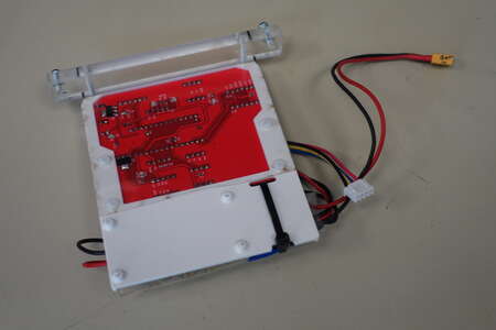
Besides the two I2C connectors there are two for SPI on the board as well.
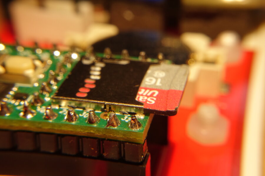
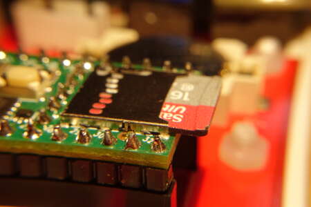
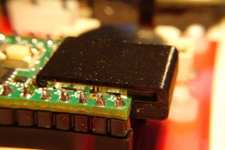
For one of them a SD card is planned.
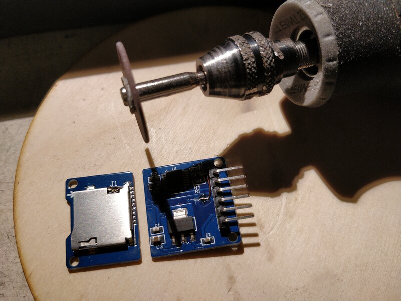
For space reasons the SD card module had to be cut. More on that soon.
The separated connections were restored with enamelled wire and stranded wire.
The module part with the level shifters modified to 3.3V is plugged directly onto the PCB.

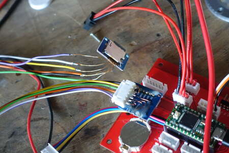
Why did the module have to be cut up?
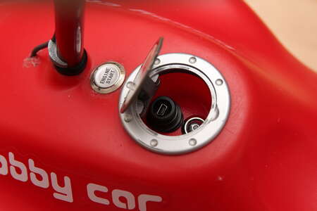
The tank cap previously contained the USB port for programming the Teensy and a push switch for switching modes.
I took out the switch because I rarely use it and it was hard to reach.
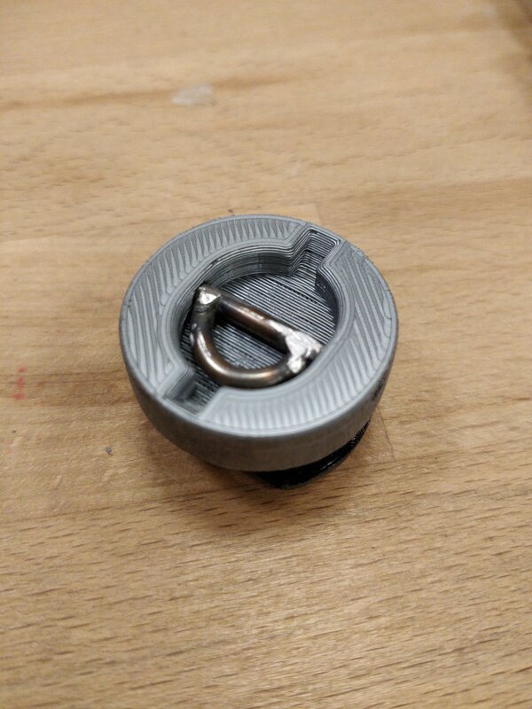
Instead, the micro SD card is to be hidden in the fuel cap.
I usually have to take this out at the earliest at the end of a day or for debugging.
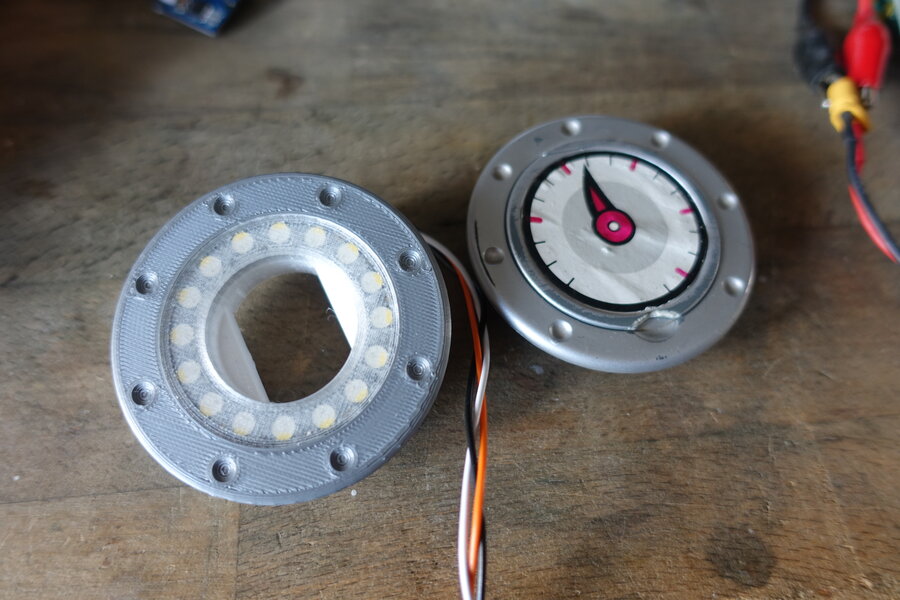
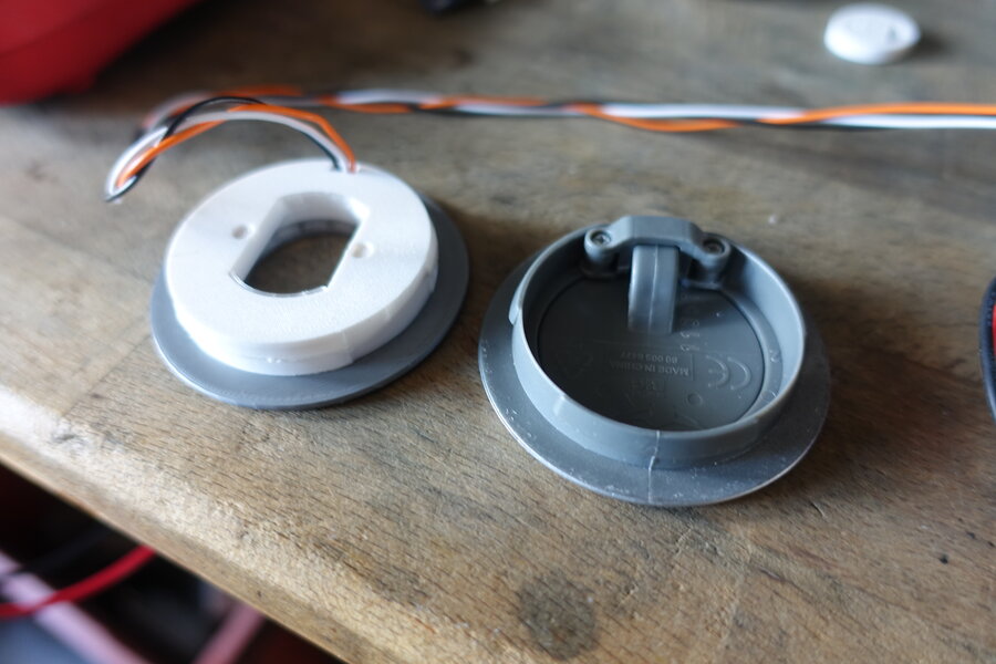
However, this still does not explain the new construction of the entire fuel cap as seen in the photos below.
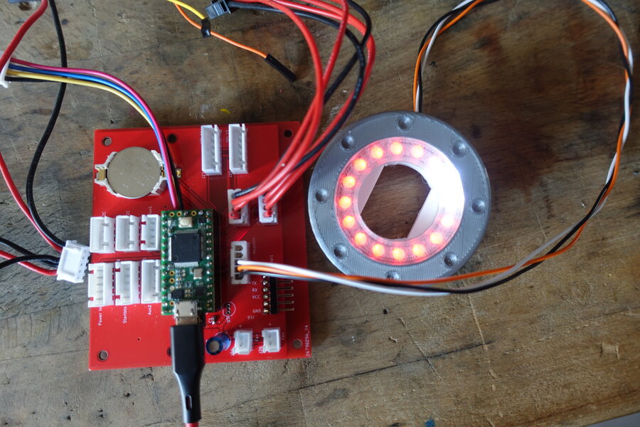
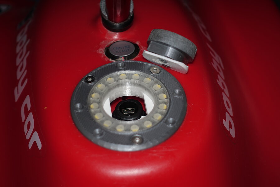
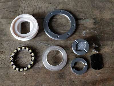
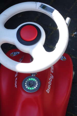
While shopping for a few other projects, I came across the Adafruit Neopixel rings.
The 16 pixel ring would fit great on the fuel cap and could display all sorts of things, such as battery voltage or error codes.
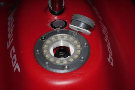
With Freecad and a caliper I started drawing. A few iterations later I had a design with a tank plug and space for the LEDs.
The plug is locked in place by turning it 90 degrees and makes a super satisfying click.


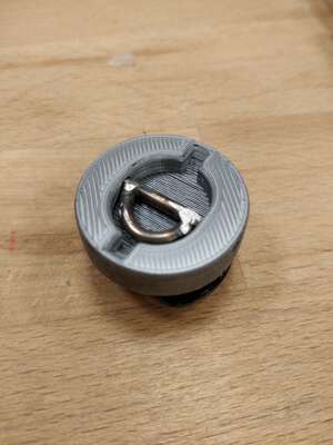
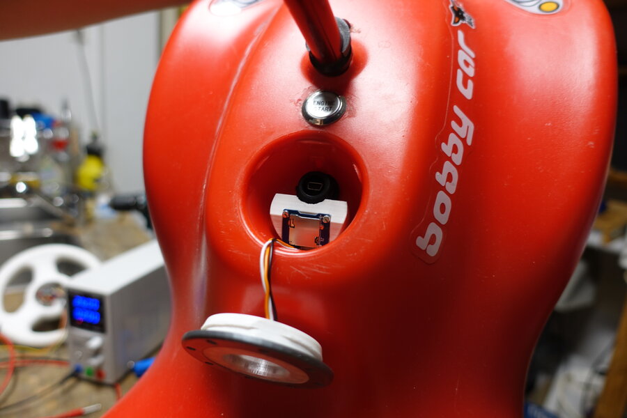
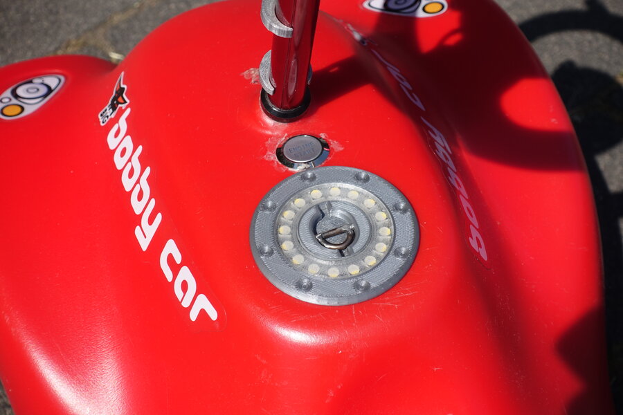
Coding went without problems and the ring now lights up.

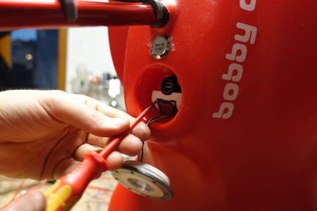
It was a bit fiddly to feed the many cables through the existing hole where the switch was previously screwed in.
The SD card is inserted at an angle from above through the small hole in the tank cap.
Without shortening the module would not have fit at all and is already super tight.


When driving, the fuel cap is unfortunately somewhat covered by your own body and not easy to see.
Nevertheless, a useful addition, in my opinion.

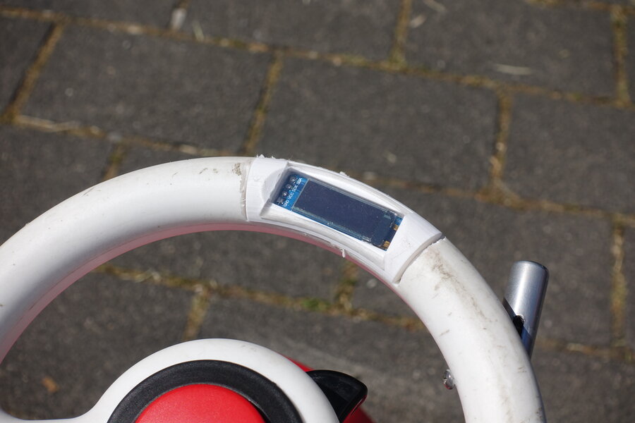
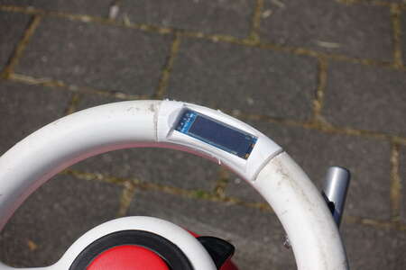
As already written, with the A/D converter in the steering wheel there is now I2C available.
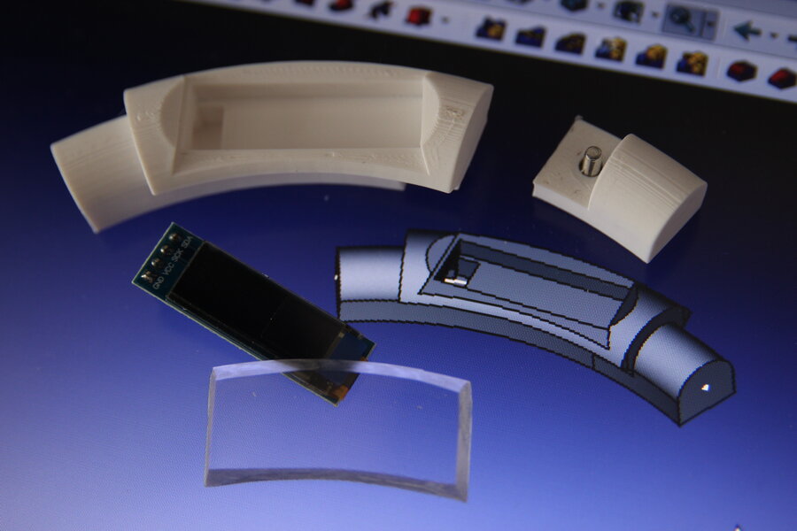
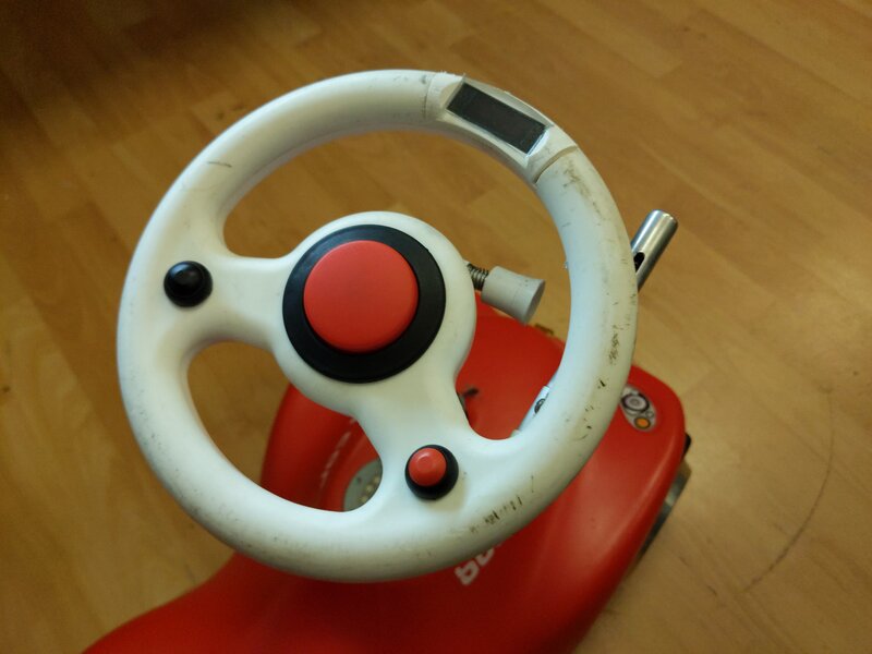
What else is there with I2C? Exactly, OLED displays.
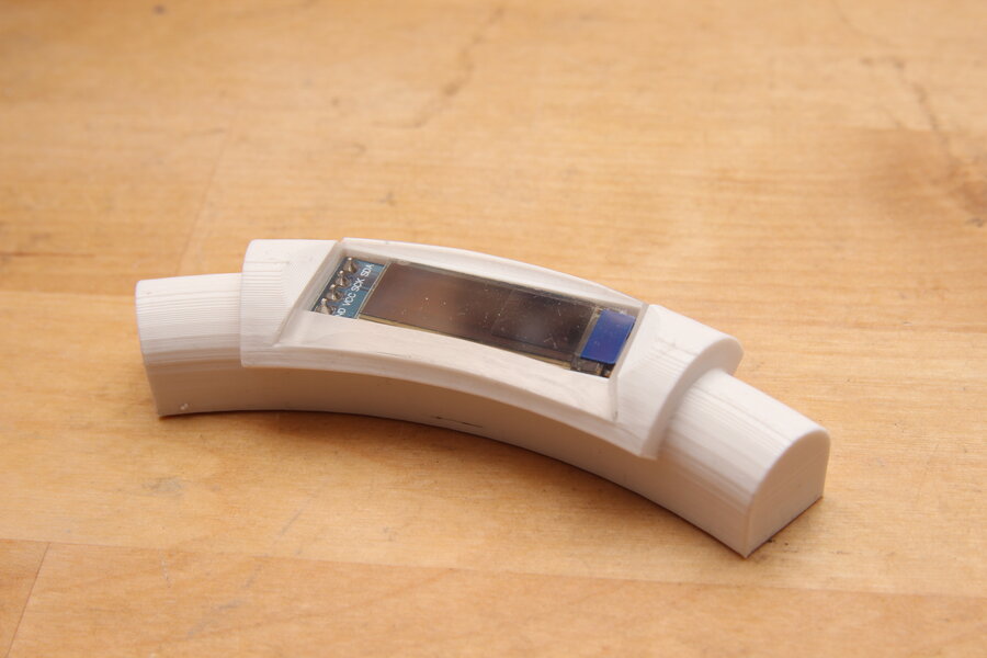
And such a display with 0.91" and 128x32 pixels fits perfectly to the edge of the steering wheel.
In my opinion, an additional attachment takes the look too far away from the bobby car, which is why it should be mounted flush.
Knowing the radius of the steering wheel and the shape of the cavity, I was able to draw an insert that holds the display behind a sheet of acrylic glass. The cables come out through the print on the left.
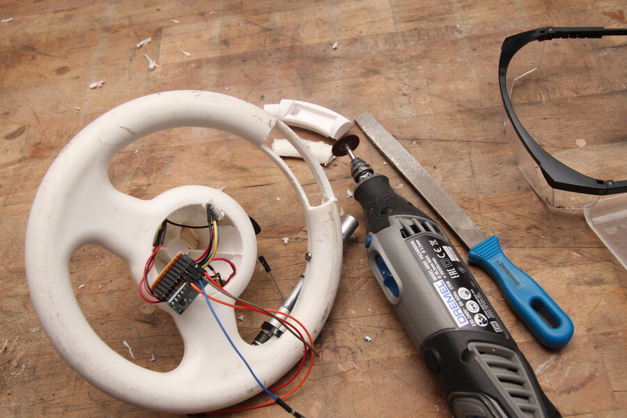
Using a cut-off wheel on the Dremel, a suitable window was carefully cut out and filed to fit.
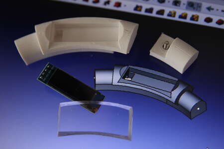


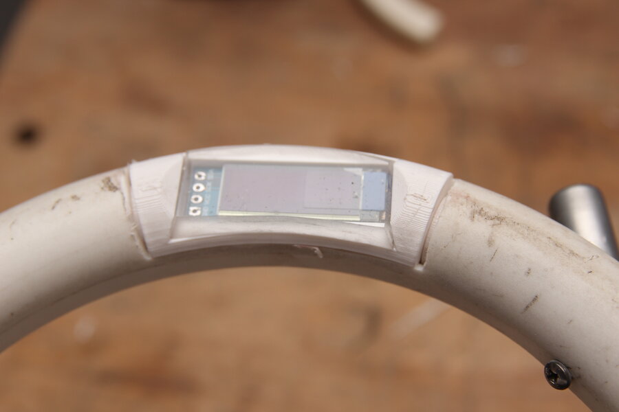
The display is inserted from the top with its encasing. The small pieces on the right is screwed in from underneath and keeps everything from falling out.

Besides the LED ring for simple status information, I can show concrete numerical values in the display:
Speed, current consumption, average consumption, battery voltage, kilometers driven, energy consumed, etc.
One of the hoverboard boards has some problems with the temperature measurement and jumps several degrees up and down.
The temperature measurement is measured on the STM32 and not on the mosfets or the aluminum plate.
Also, calibration is very cumbersome and not very accurate.
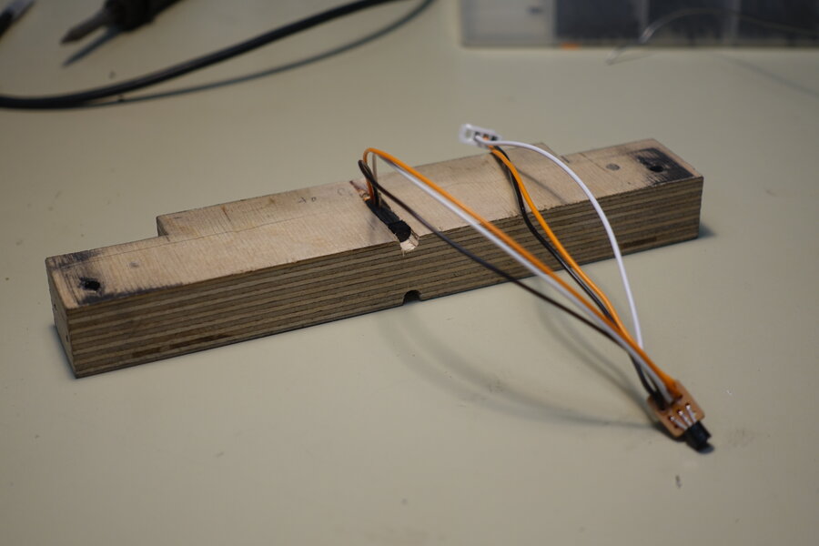
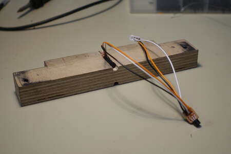
The schematic already showed the three DS18B20 1Wire temperature sensors connected to one of the unused connectors.
Two of them are embedded in the wooden piece with contact to the aluminum plates of the mainboards, the third one will hang freely in the belly of the Bobbycar.
A few months earlier, I had already installed two 40mm fans to the left and right of the hoverboard boards to force some air circulation inside.
At that time, I still believed the warning sounds and assumed the temperatures were too high.
These fans are now turned on via transistors when the temperature rises. The fans are actually not necessary.
During my last longer drive in summer temperatures, 45°C was reached only once for a short time.
That was exactly the threshold at which the fans would have come on.
The acoustic beat of the two fans sounds like a network switch. That's actually quite nice, too.

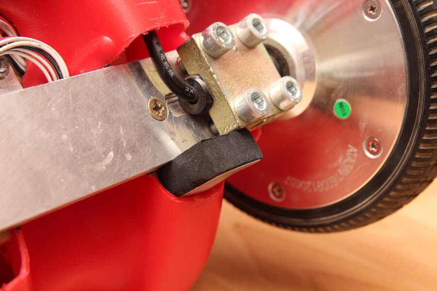
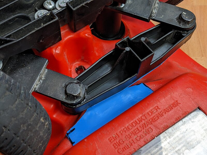
At some point in between, sliding pads were glued to the two rubbing surfaces of the tie rod to the main body.
I had previously used lubricant. However, sand and dirt quickly accumulate there, which then abrades the plastics in the long term.


Throttle and Brake Lever
Sitting on such a bobby car requires a high level of confidence in the mechanical, electrical and software systems.
Especially if you were responsible for all three yourself.
The thought of what happens if component X has fault Y occurs to me quite often. Most of the time, fortunately, it simply leads to a standstill with or without a subsequent hardware defect.
Others, on the other hand, can be mitigated by some advance planning in the software and trigger a fail-safe.
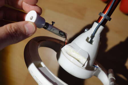
Let's take a look at the linear Hall sensor on the throttle lever.
The magnet is moved back and forth along the Hall sensor by pressing it with your finger.
The calibration covers the expected minimum and maximum values. Above and below this, a dead zone is included in which the calculated value does not change any further.
If one of the three cables to the Hall sensor (GND, VCC or signal) becomes disconnected, the measured value is far outside the dead zone and an emergency stop (stop category 2) is triggered by the software.
But what happens if the hall sensor comes loose or outputs an incorrect signal? The signal could be somewhere in the valid range.
The result is that the Bobbycar continues to drive unintentionally.
I felt that I had not paid enough attention to this error case so far.
My solution was the same as the one already implemented for the
Hoverbrett: determine the same measured value using two sensors.
If the measured values deviate too far from each other, the failsafe is triggered.
In addition, the resolution is higher, as the average value of both sensors can be used for further calculations in normal operation.
A lot of text, simple implementation.
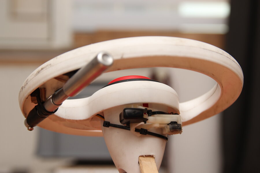
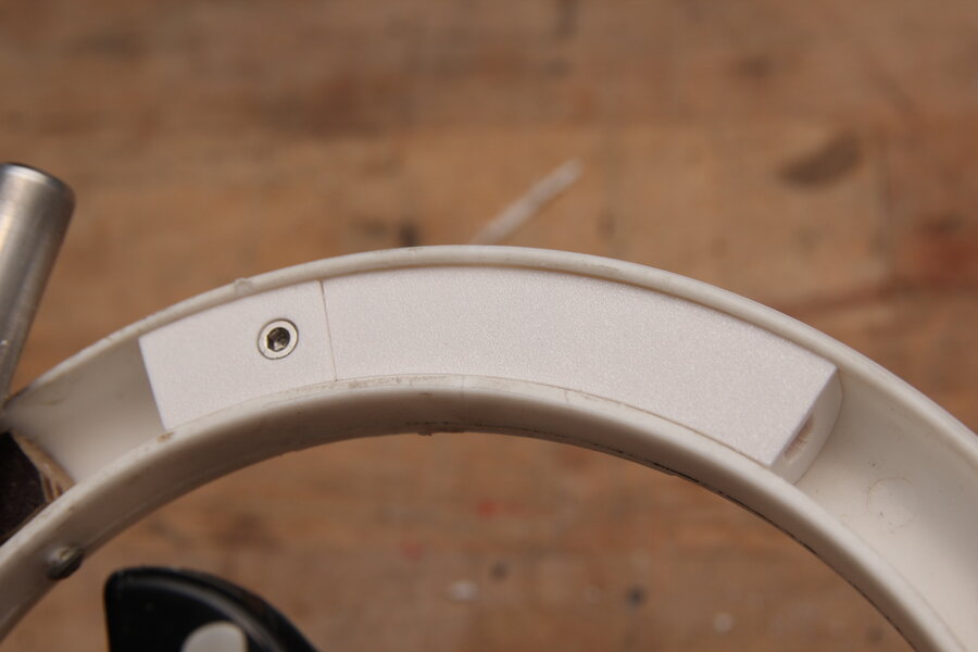
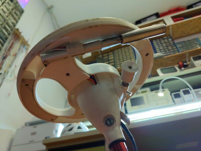
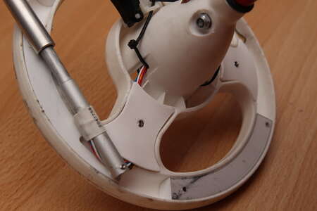
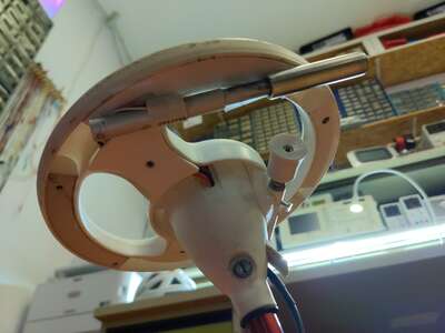
I took this opportunity to improve the mounting on the underside of the steering wheel.
I already had the CAD drawing of the steering wheel arch from the display.

I also didn't find the open cable routing particularly attractive or safe.
Figuring out the dimensons for the cover was a bit more complicated. After a few test prints, however, I was satisfied.
I used the blind hole in the stiffening frame to clamp the cover in place with a grub screw.
After I had rebuilt the throttle lever, the X-Box shoulder button was converted into a brake lever.
Unfortunately, this has now happened, which is why I started the conversion to hall sensors as a precaution.
The potentiometer grinds and does not provide a clean signal. The aforementioned failsafe was also installed here and now occasionally causes an unintentionally standstill. Annoying, but still a good thing.
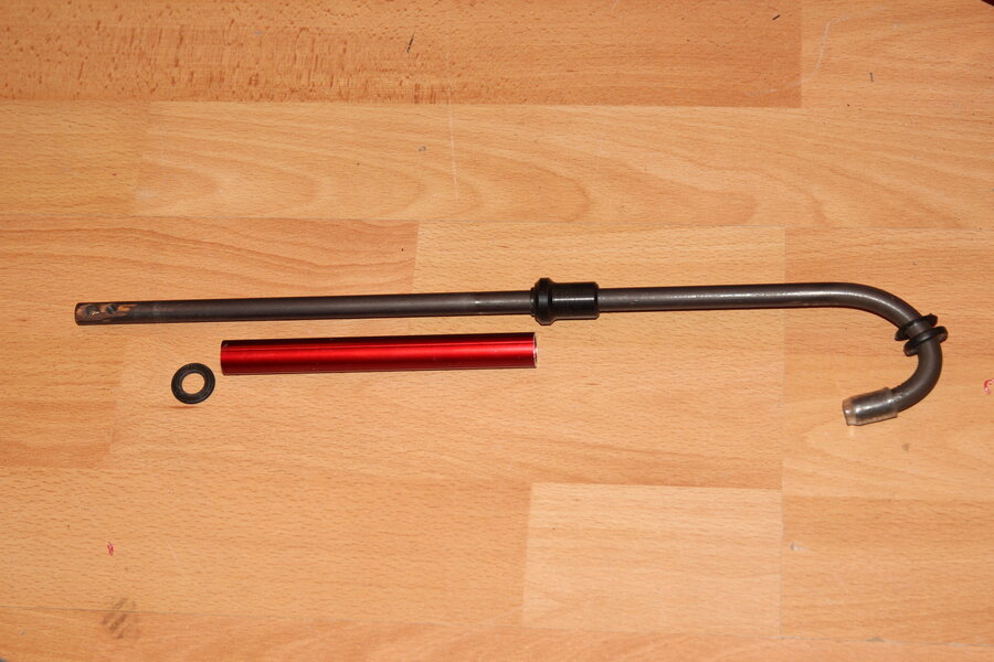
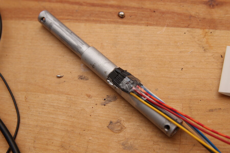
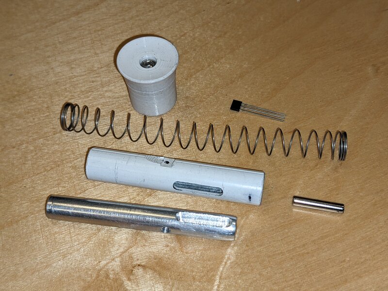
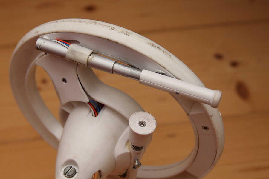
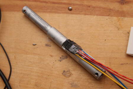
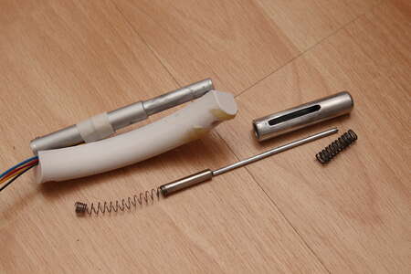
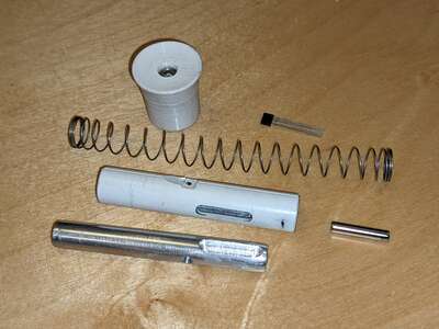
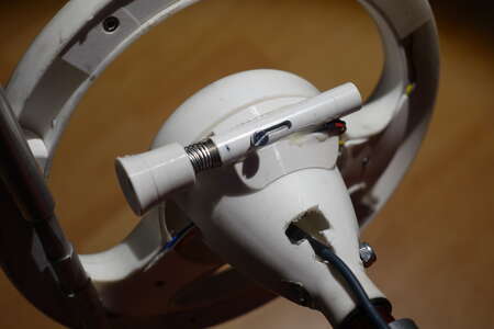
That's why I had to build a new brake lever. I implemented this mechanically in a very similar way.
This time the 15mm long bar magnet (3mm diameter) is embedded in the aluminum rod.
A screw on the side provides the end stops by sitting in a slotted hole in the outer PVC pipe.
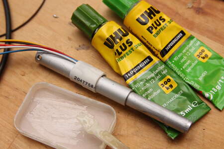
The Hall sensor is again glued to the outside of the PVC pipe using epoxy glue.
I do not use a second Hall sensor for the brake. If the brake is triggered, the Bobbycar decelerates anyway. The speed in reverse is also very limited.
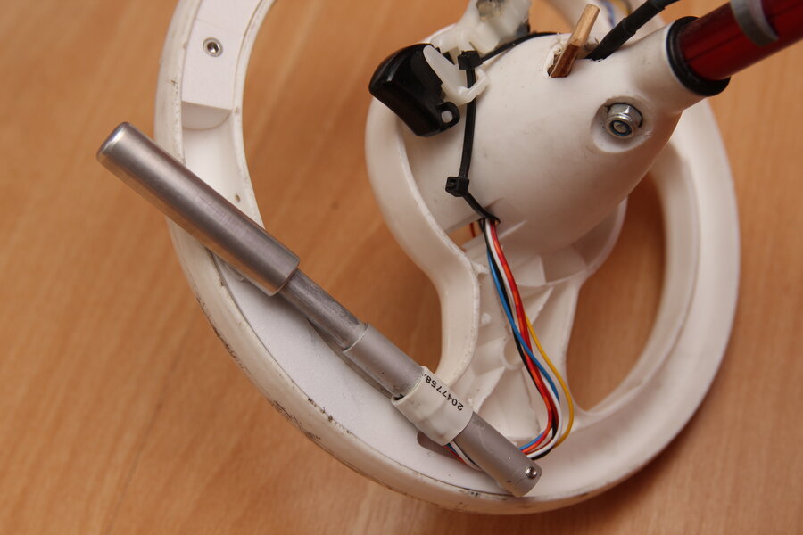
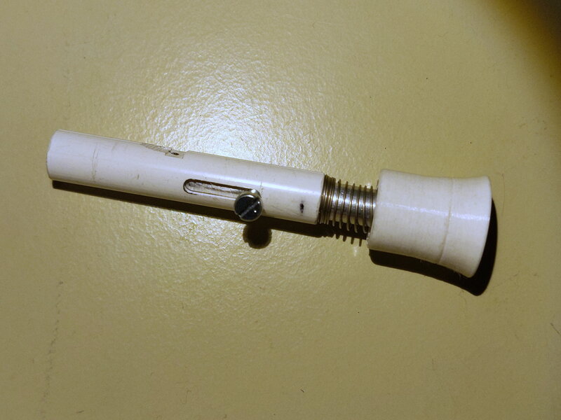
There is a ergonomically shaped end cap on the finger side. It is held in position axially by an M3 screw with thread in the aluminum rod.
Between the end cap and the PVC tube, a rather soft but long compression spring ensures that the lever is pushed out by itself.
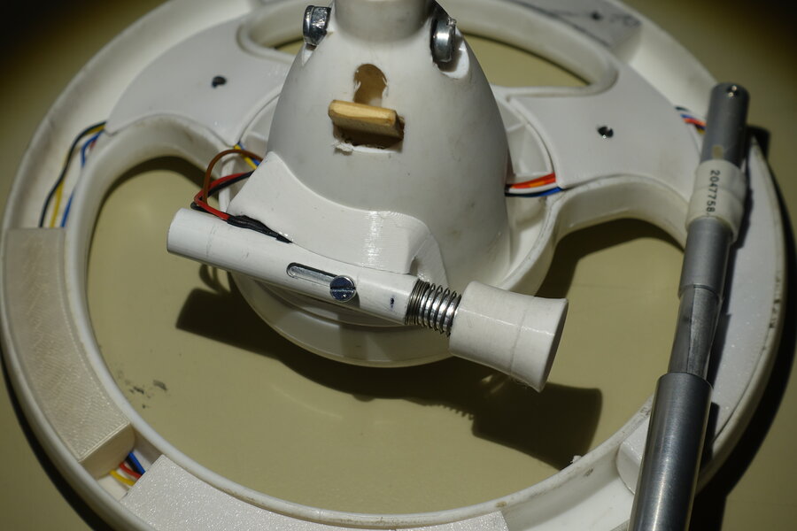
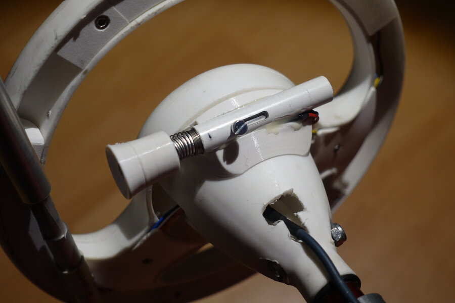
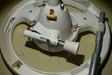
Adapted to the shape of the steering wheel, there is a 3D printed part which partially encloses the new brake lever. 2-component epoxy glue again ensures a firm bond.

So far, the Bobbycar can only be operated using an on/off button and the accelerator and brake levers.
Even if I would rather not have menu navigation on the Bobbycar at the moment, a little more interaction would be helpful in some situations.
For example, switching to a slower mode or displaying further information on the small OLED display.
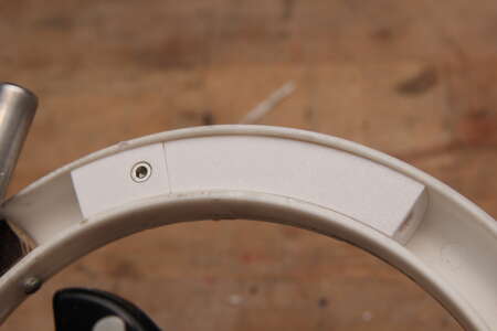
To do this, I looked for two buttons that didn't stick out too far, especially on the connection side.
There were only two possible positions for the 12 mm holes between the stiffeners.
One channel was still free on the 4-channel ADC in the steering wheel.
As long as I don't need it for other functions, I use it for these two buttons.
With different resistor values, distinct voltages are possible for the four states (no button pressed, left button pressed, right button pressed, both pressed).
Below is the circuit diagram of what is in the steering wheel.
A circuit diagram of the entire Bobbycar at the time of March, 2nd, 2024 as PDF: 20240302_Bobbycar_Wiring.pdf


In the meantime, I've gotten used to this unusual way of operating the accelerator and brake with my right hand.
It looks a bit like trying to determine the direction of the Lorentz force.

Because the throttle lever is rubbing two aluminium parts against each other some deposits can now be seen.
Also because it wasn't that straight anymore and got stuck sometimes it got replaced by a PCV tube.

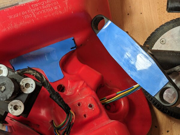
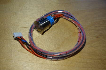
Somewhere inside the bobby car, the cable to the start button had rubbed and short-circuited to the status LED.
At first I suspected the button itself, which is why it was replaced immediately.
However, when it was removed, it turned out that the cable itself needed better protection.
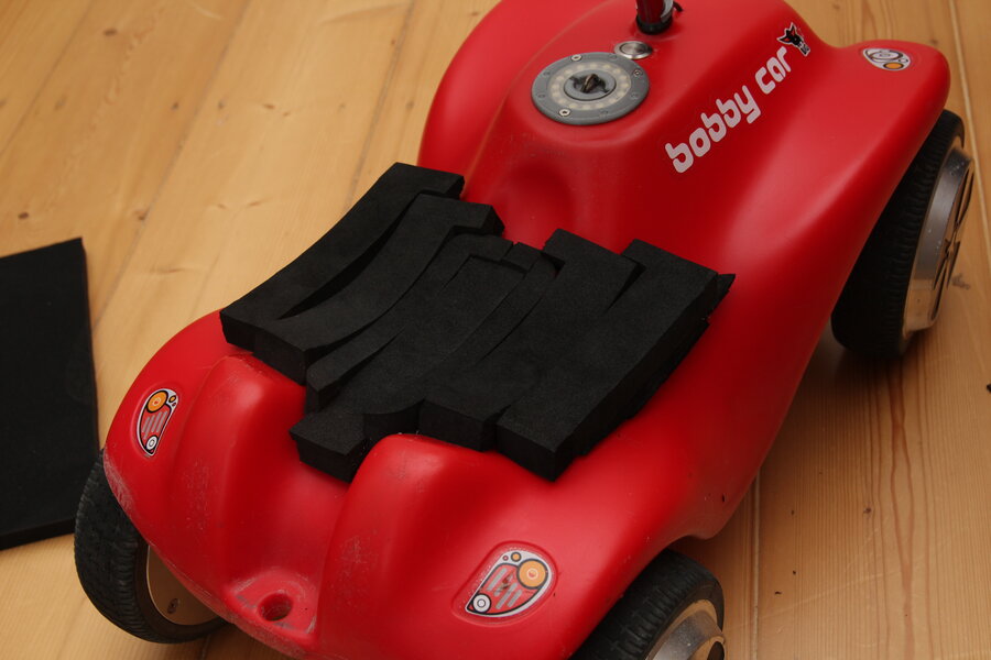
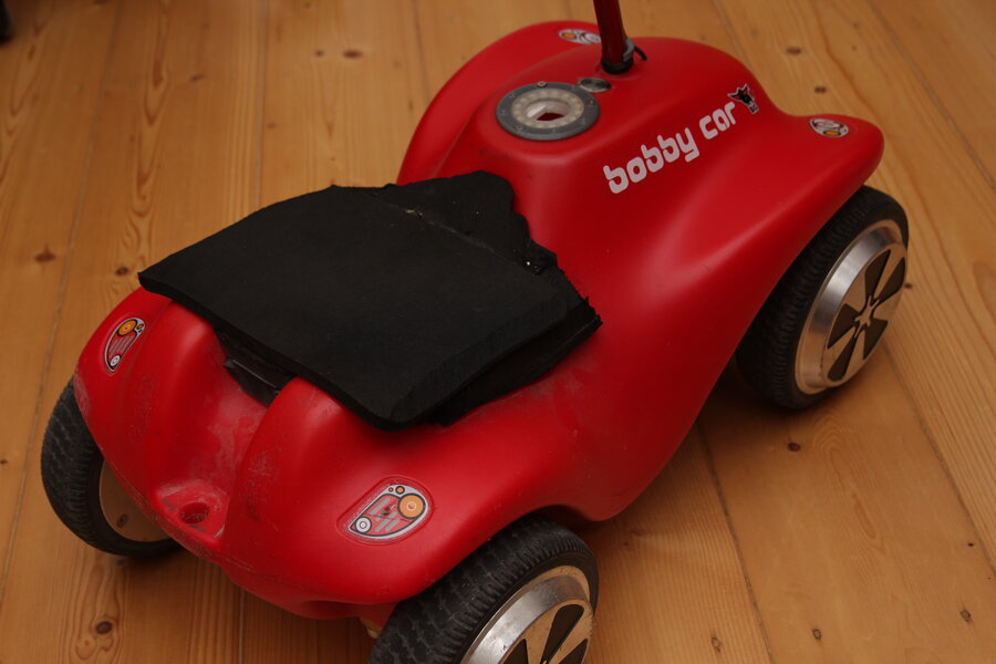
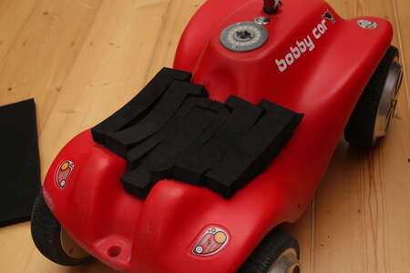
Until now, a seat cushion helped me to make the longer journeys a little more bearable.
It was only when I forgot it, I could feel it for a few more days.
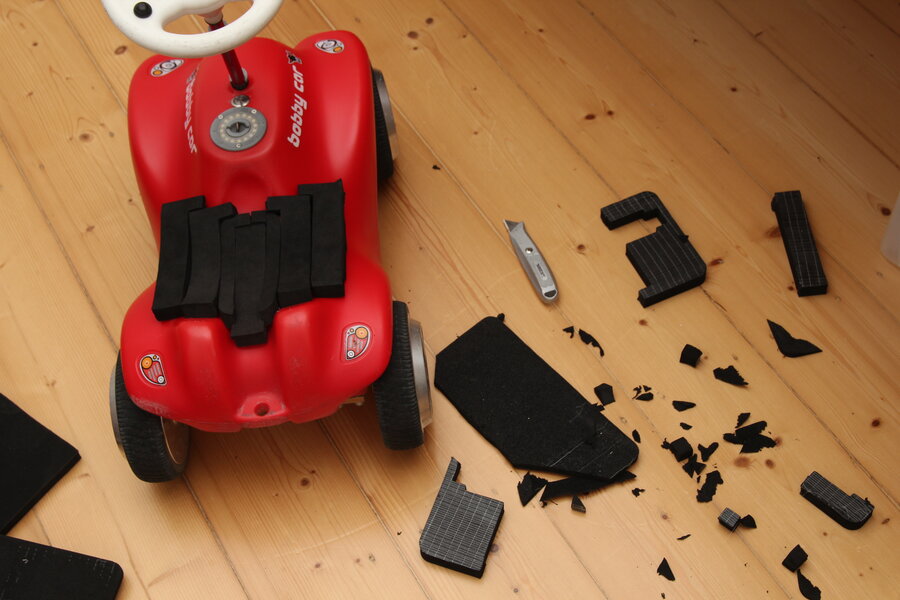
Some rather firm packaging foam fell into my hands, some of which still had an adhesive surface.
I was able to carve out a seat base from several small pieces. I used UHU Por where necessary.


Teensy 4.1
I decided on the Teensy 3.2 at the time because I was already using one in another project and the spare parts supply was better for me.
Then came the chip shortage and shortly afterwards the Teensy 3 was discontinued by the manufacturer.
Before I got into the predicament of having to replace a defective Teensy 3.2 in the bobby car at short notice, I wanted to switch to hardware that was still available.
The Teensy 4.1 is much better and faster anyway and can do much more.
However, the new circuit board has remained largely the same.
 20240628_Bobbycar_wiring.pdf
Git Tag 20240628
20240628_Bobbycar_wiring.pdf
Git Tag 20240628

It is worth mentioning that I am now using the micro SD slot on the Teensy and have removed the SD holder in the fuel filler cap.
There is new an interface in the code that can be used to transfer the content of the SD card via USB serial.
This means that there is no longer any need to remove the memory card.
However, the micro SD card is only held in place by friction.
A printed cover is clipped onto it and hopefully prevents it from falling out.
Bobbycar Git: git.ctdo.de/interfisch/bobbycar
 Bobbycarbau