CrazyCart
März 2015
Inhaltsverzeichnis
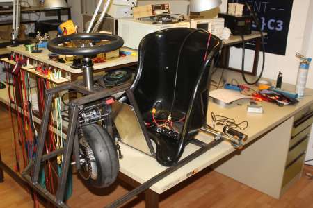
Das Crazy Cart von Razor ist ein relativ kleines Kart, mit einem Elektromotor am Vorderrad und zwei “Einkaufswagenrollen” als Hinterräder, welche sich über einen Hebel nach hinten kippen oder gerade stellen lassen. Zieht man also am “Drift-Hebel”, werden diese gerade gestellt und erlauben es ohne durchdrehende Reifen um Kurven zu driften.
Nachdem ich die Möglichkeit hatte einmal auf einem nachgebauten CC zu sitzen war sofort klar: MUSS HABEN!
Neben dem Crazy Cart gibt es auch das Crazy Cart XL für Erwachsene. Im Owners Manual des Razor Crazy Carts gibt es glücklicherweise Explosionszeichnungen, die sollten beim Eigenbau helfen.
Statt 300W (bzw. 500W beim XL) soll es für den Eigenbau etwas mehr sein: 2,5kW sind angestrebt. Dafür ist eine stabile Konstruktion essentiell, 20x20x2mm Stahlprofile sollen für den Rahmen zusammengeschweisst werden. Die restlichen Bauteile sind größtenteils von Kartshops zu beschaffen.
Auch ist ein Brushed Motor nicht der richtige Weg, ein Brushless ist viel effizienter und deutlich kleiner. Die Ansteuerung des 3-Poligen Brushlessmotors übernimmt ein Brushlesscontroller (weiter unten dazu mehr), der seinen Saft von einem Set LiPo Akkus aus dem Modellbau bekommt. Um 2500 Watt zu erreichen wird ein 12S Lipo benötigt, der dann 50A Spitzenströme abgeben soll. Da ein 12S Lipo schwer zu bekommen/teuer ist, tun es 3x 4S 5Ah Lipos in Reihe genausogut.
Das ganze Projekt wird ein mehr drauflos bauen sein, von daher wird der Baubericht meist in der Reihenfolge sein, in der ich die Sachen gebaut hab. Änderungen im späteren Verlauf sind also durchaus möglich.
Angefangen hab ich damit 90% der Teile zu kaufen, da es deutlich einfacher wird beim Bau, die Sachen direkt dranhalten zu können, um zu sehen, ob das so zusammen passt.
Auch da ich bei so vielen verschiedenen Shops ordern musste, hätte es theoretisch passieren können, das ein Teil nicht mehr zu bekommen ist, sodass ich umplanen hätte müssen.
Brushless controller
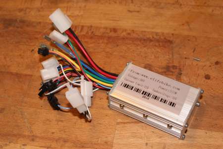
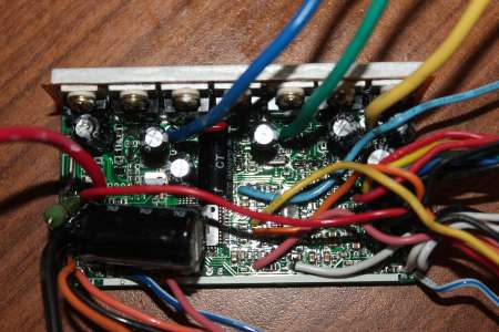
Wie dem auch sei; Fangen wir an mit dem Brushless Controller, welcher da ist ein sogenannter Jasontroller. Für etwa 25 euro incl. Versand von Elifebike: E-Bike Motor Controller.
Wer sich da etwas einlesen will: www.etotheipiplusone.net
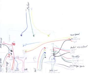
Was die ganzen Kabel aus dem Kabelbaum des Controllers zu bedeuten haben kann man in dem Wiring Diagram nachschlagen.
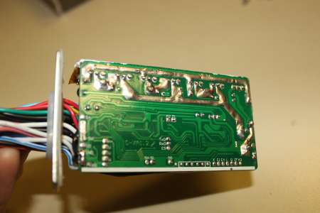
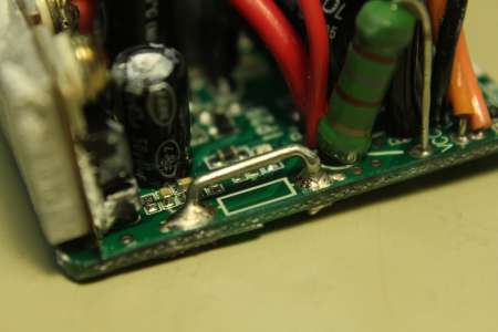
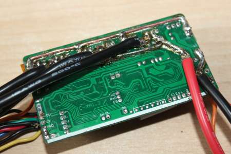
Wie bei ELifeBike zu sehen ist, ist der “Mini Jasontroller” mit 36V/48V und 500W angegeben, meine Variante ist mit 350 Watt etikettiert, was aber eigendlich egal ist, da die Controller sich nur im verbauten Shunt unterscheiden. Um dem Stück Technik etwas mehr Leistung zu entlocken kann der Shunt (die kleine Widerstandsdrahtbrücke am Rand des PCB’s) etwas minimiert werden, sodass der Spannungsabfall geringer wird und so die Strombegrenzung des Controllers erst später einsetzt.
Durch Messen des Spannungsabfalls direkt am Shunt bei 1A Stromfluss konnte ich diesen Originalshunt bei dem 350W Controller auf 6mOhm bemessen. Mittels Dreisatz wird ein Shunt von 0,84 mOhm für 2,5kW benötigt. Lässt man den 6mOhm Shunt eingebaut und lötet parallel dazu einen 1mOhm Shunt ein… 1/6mOhm + 1/1mOhm = 1/Rges … Rges=0,857 mOhm … kommt man auf etwa 0,86 mOhm, sollte passen.
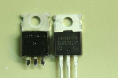
Damit die verbauten Mosfests (RU6888R, Datasheet) nicht sich und den Rest des Controllers in Rauch auflösen, hab ich diese 6 billig Mosfets direkt durch IRFB4110 (Datasheet) von Reichelt ersetzt.
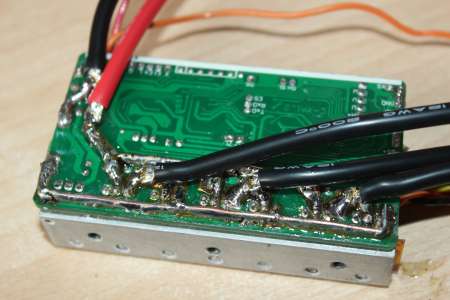
Später werde ich noch ein paar der Kabel ablöten und vorallem die Kabel vom Akku und zum Motor durch deutlich dickere Silikonkabel 10AWG - 12AWG ersetzen, sowie die Leiterbahnen durch die der Großteil des Stroms fliesst mit Kupfer vergrößern.
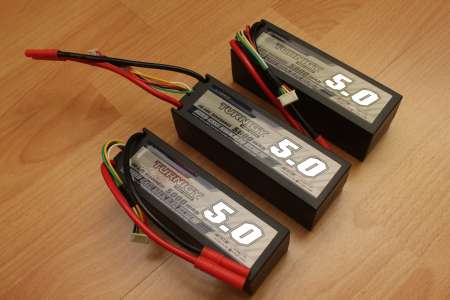
Die Akkus die ich zum Antrieb verwende sind 3x 4S 5Ah 20C Lipos von Hobbyking. Da ich nicht auf die vollen 20C angewiesen bin (20C * 5Ah = 100A) reichen mir die allergünstigen: Turnigy 5000mAh 4S1P 14.8v 20C Hardcase Pack.
Die 4mm Bullet Stecker werde ich durch XT60 ersetzen. Passenderweise kann ich den weiblichen Teil der 4mm Bullet Stecker ausbauen und für den Motor verwenden.
Eine Zelle von einem der Lipos hatte nur 3,2V als diese bei mir ankamen; 3,9V hatten alle anderen Zellen. Nach dem Laden der einen Zelle auf 3,9V konnte ich keine Beeinträchtigung des Lipos mehr feststellen.
Motor
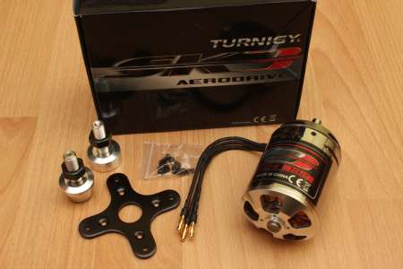
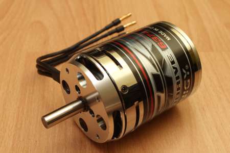
Der Motor ist ein Turnigy Aerodrive SK3 mit 192KV und 2,75kW maximaler Leistung.
Der Aussendurchmesser beträgt 58mm, die verlöteten Stecker sind 4mm Bullet Connectors.
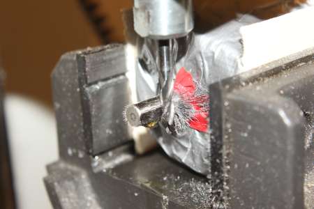
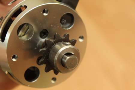
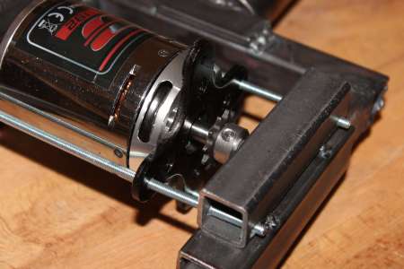
Damit das 11 Zahnige 25H Ritzel auf die 8mm Welle passt, musste ich diese ein paar mm weit anflachen. Mit Schmieröl und in der CNC eingespannt konnte ich in etwa 1/10mm Schritten solange Material abfräsen, bis das Ritzel gerade so drauf passt.
Der 8mm Stellring hindert das Zahnrad am herausrutschen.
Der Jasontroller hat die wunderbare Funktion bei niedrigen Drehzahlen und beim Anfahren die Position des Rotors anhand von Hallsensoren zu ermitteln, wodurch der Controller nicht den Motor ruckartig bewegen muss um zu wissen, wie er diesen bestromen soll.
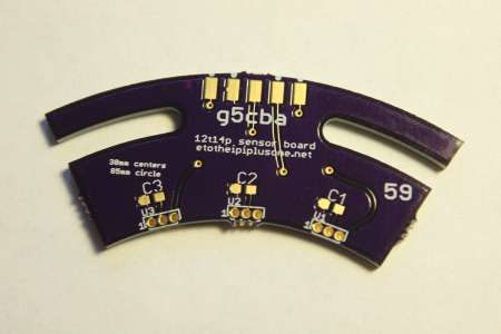
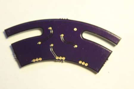
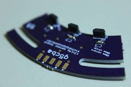
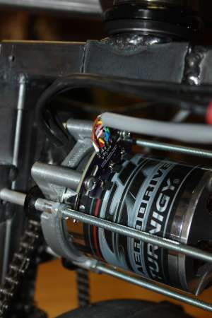
Ein fertiges PCB mit Hallsensoren gibt es bei e0designs.com zu kaufen. Auch eine Aufbauanleitung gibt es dazu.
Da die Eaglefiles für das Board frei zur Verfügung stehen konnte ich eins über eine Sammelbestellung bei einem PCB Hersteller günstig bekommen. Die ATS177 Hallsensoren (3 werden benötigt) konnte ich nur bei Digikey bekommen, ebenso wie die SMD Shunts für den Controller (siehe weiter unten).
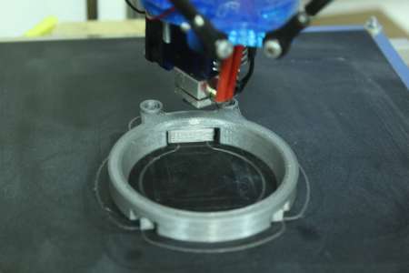
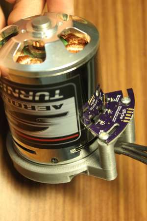
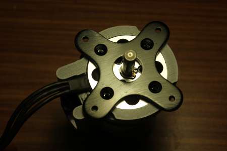
Den Adapter zum Montieren des Sensorboards gibt es auf der Seite auch als STL download zum 3D-Drucken. Dieser wird auf den Motor geschoben und durch das dem Motor beiliegende Befestigungskreuz gehalten. Durch die Schlitze an der Platine kann diese ein paar mm justiert werden. Dies wird später noch beim exakten Einstellen eine Rolle spielen.
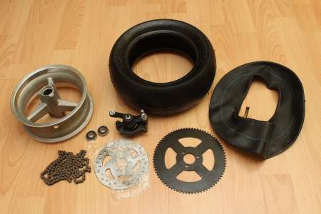
Weiter gehts mit dem Vorderreifen. Kurze Teileliste der im Bild dargestellen Teile:
- Felge 6,5" ritzelladen
- Kettenrad 78 Zähne ritzelladen
- Schlauch 90/65 - 6,5 Happy-Motor-Parts
- Reifen Pocket Bike vorne 90/65 - 6.5 Slick Happy-Motor-Parts
- Bremsscheibe Pocketbike 120 mm (Typ 2) Happy-Motor-Parts
- Kette 25H Pocketbike 73 Glieder Happy-Motor-Parts
- Kettenschloß 25H füR 3mm starke Kettenräder ritzelladen
- Bremse (ähnlich) pocket-motor-bikes
- 2x 10x26x8mm Kugellager ebay
Die hier aufgeführen Läden sind nur Beispielbezugsquellen. Manch der Teile sind bestimmt günstiger woanders zu bekommen, wo sie zu meinem Bestellzeitpunkt nicht verfügbar waren.
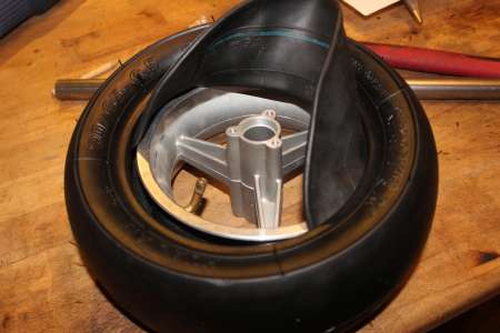
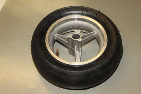
Die Felge zu beziehen war nicht ganz einfach, aber hat am Ende doch geklappt. Das Ventil bekommt demnächst noch eine Kappe, damit sich dort kein Dreck ansammelt.
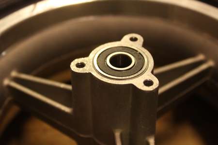
Damit das 26mm Kugellager (26mm aussen, 10mm innen) in die Felge passt musste ich etwas Material von der Felge abkratzen, der Rest ging mit Brett und Hammer ganz gut.
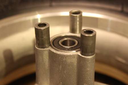
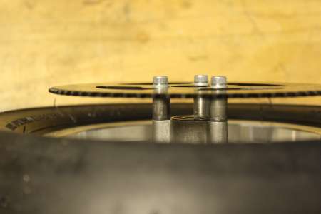
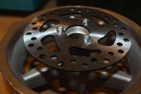
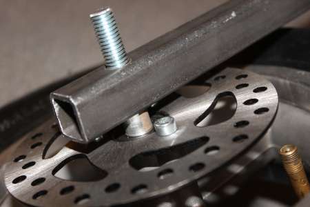
Auf der Seite, an der das Kettenrad befestigt wird mussten noch drei Abstandshalter angebracht werden, damit die Kette nicht am Gummi kratzt. Die Bremsscheibe wird auf der gegenüberliegenden Seite angeschraubt. Dort musste ich noch die drei Löcher in die Felge Bohren und das M5 Gewinde schneiden.
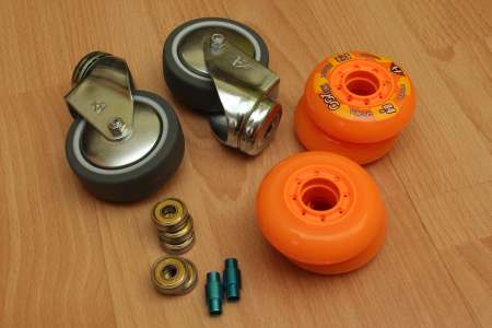
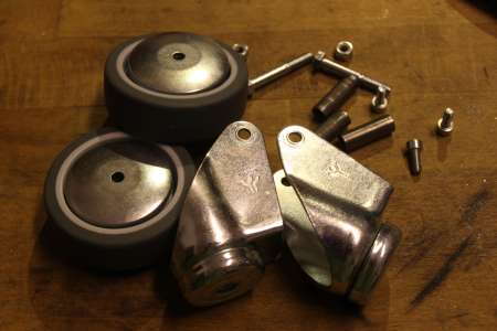
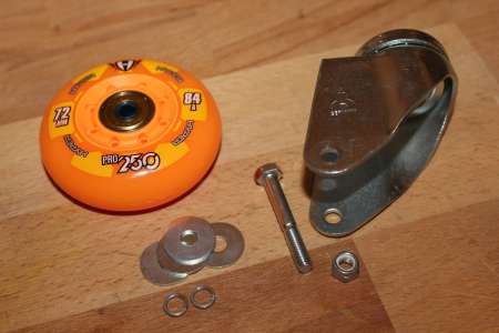
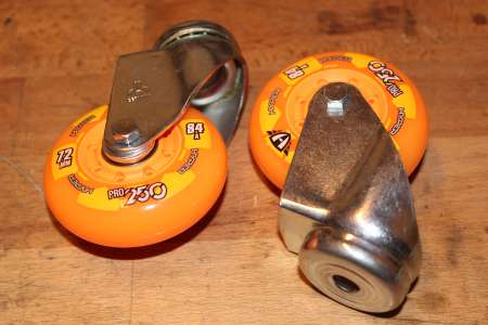
Die drehbaren Hinterräder sind wie folgt zusammengesetzt:
- Apparate-Lenkrolle Hornbach
- Hyper Pro 250 [72mm 84A] Skatepro
- min 4x 608ZZ KugellagerSkatepro
- Powerslide Spacer 6mm Skatepro
Von den Lenkrollen wird nur das Gestell und das Lager benötigt. Die Kugellager sowie die Spacer werden in die Skaterollen eingesetzt.
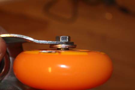
Mit ein paar Unterlegscheiben als Abstandshalter können die Rollen dann eingesetzt werden.
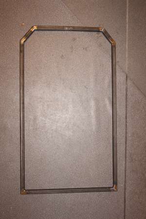
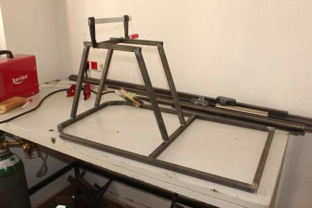
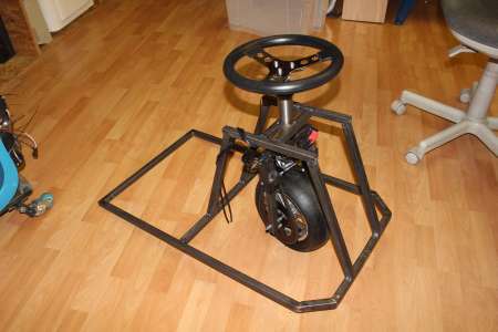
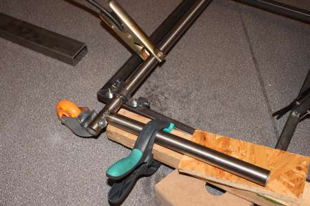
Nun gings an den Rahmenbau aus 20x20x2mm Stahlprofilen. Der Rahmen ist aussen gemessen etwa 500mm breit und 900mm lang.
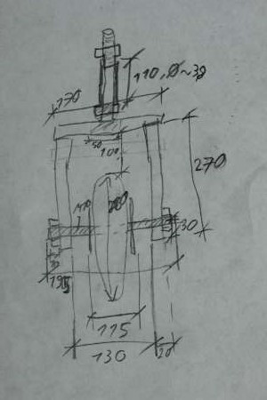
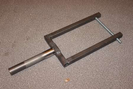
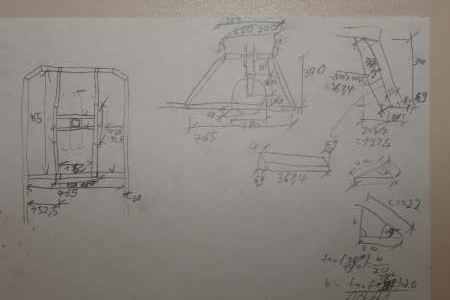
Die Gabel für den Vorderreifen ist 270+20mm hoch und innen 130mm breit. Der Vorderreifen wird unten auf eine M10 Gewindestange gesteckt.
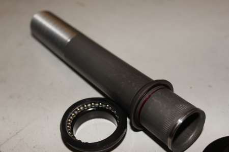
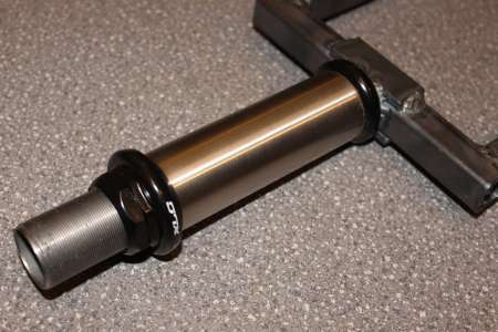
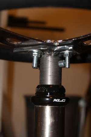
Damit das Vorderrad drehbar ist, wird auf die Gabel ein 1 1/8" Gabelschaft angeschweißt.
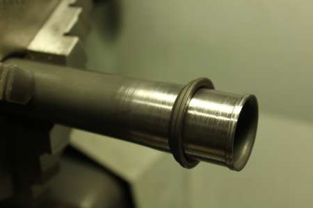
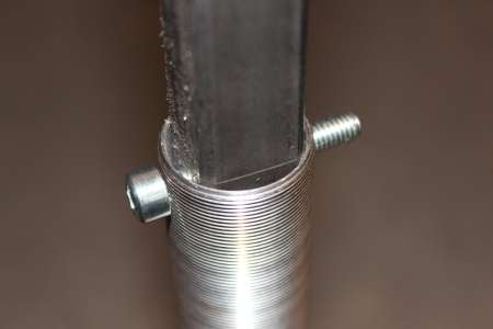
Dieser musste am unteren Ende ein paar 1/100mm abgedreht werden, damit der untere Ring des Steuersatzes bis unten draufgeschoben werden kann.
Nachtrag: Das Runterdrehen stellte sich als eher schlechte Idee heraus, da mir das Teil exakt an der Stelle später beim Fahren weggebrochen ist. Siehe Crazycart 4: Gabelschaft Reparatur
Danach konnte der Gabelschaft mittig auf der Vordergabel gerade angeschweisst werden.
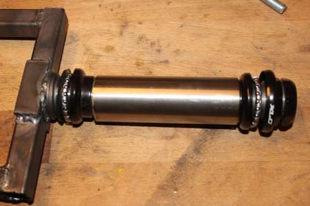
Zwischen die Hälften des Steuersatzes wird ein Stahlrohr (hier so 11cm lang) eingesetzt, welches dann am Rest des Rahmens angeschweisst wird.
Den Platz links und rechts vom Reifen auf der Gewindestange hab ich mit einem passenden Alurohr gefüllt, sodass an der Seite der Bremsscheibe die Bremse sich noch gut befestigen lässt und auf der anderen Seite die Kette zum Motor sowie der Motor noch zwischen die Gabel passen.
Und einmal meine Skizze mit den Maßen der Vorderradgabel.
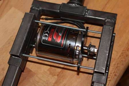
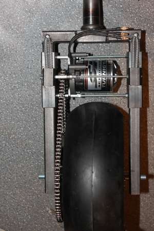
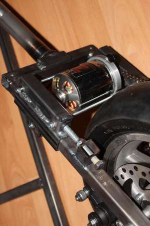
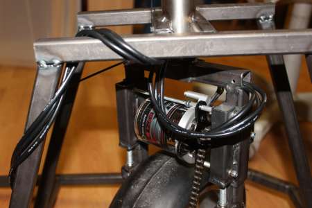
Der Motor kommt mit in die Radgabel direkt über den Motor, wo er den Reifen direkt über eine Kette antreibt.
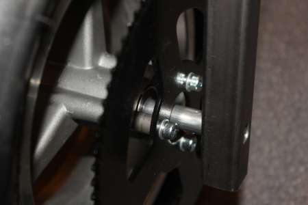
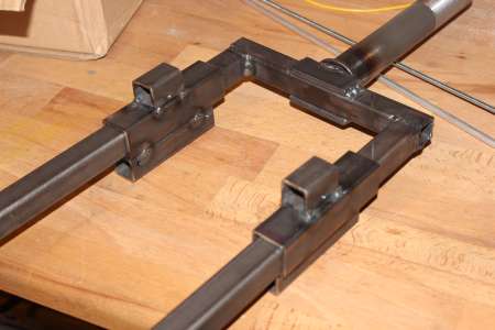
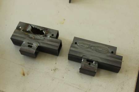
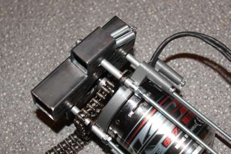
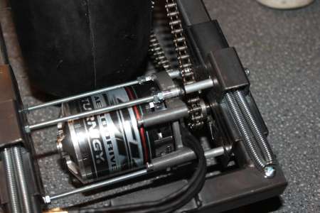
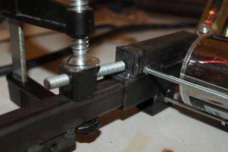
Um die Kette spannen zu können wird der Motor um ein paar centimeter nach oben und unten verschiebbar sein. Zwei größere Stahlprofile werden auf beide Seiten der Gabel geschoben, der Motor wird mithilfe des im Lieferumfang enthaltenen Kreuzes auf drei M4 Gewindestangen gesteckt und später von einer Seite mit Alurohrstücken als Distanzhülsten und Schrauben fixiert. In einen der beiden Schlitten musste ich mittig ein loch flexen/braten, da die Welle des Motors etwas zu lang ist. Besser währe es wohl gewesen, die Gabel nen cm breiter zu machen… zu spät.
Zurück zum Rahmen und der Radgabelaufhängung. Als erstes kam eine Querstrebe in den Rahmen, sodass der vordere Teil quadratische Maße und somit das Rad beim Lenken zu allen Seiten den gleichen Abstand hat.
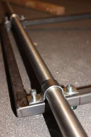
Zwei Bügel mit (innen) 20cm Abstand zueinander hab ich dazu mittig angeschweisst.
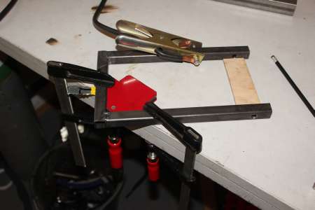
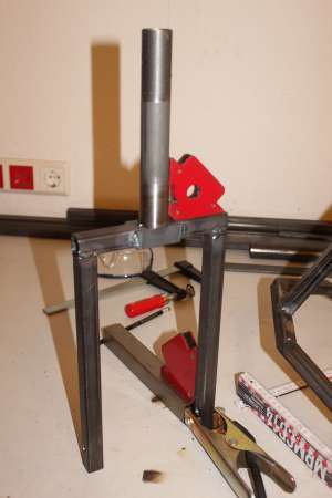
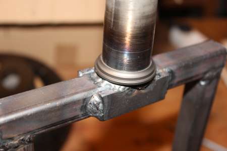
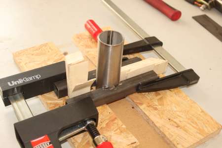
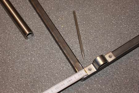
Ein Edelstahlrohr, welches exakt auf den Steuersatz passt hab ich grob zugeflext und auf 110mm abgedreht (wie zuvor bereits erwähnt), dadurch ist das Ende des Rohrs perfekt gerade. Um das Rohr zwischen den beiden Stahlbügeln anbringen zu können musste ich es erst an zwei Stahlprofile mit einer “runden” Kerbe befestigen.
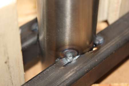
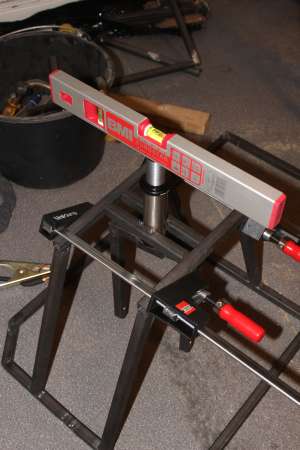
Mit einer Wasserwaage ließ sich das Rohr perfekt gerade zum unteren Teil des Rahmens ausrichten und einklemmen und anschließend festschweissen.
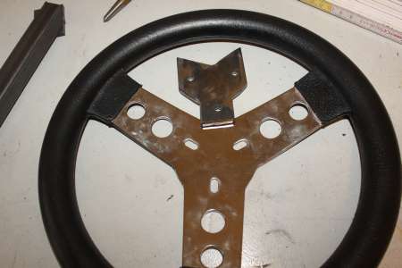
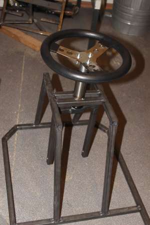
Das CC hat den Vorteil, dass man gut um kurven Driften und auch seitwärts fahren kann. Dazu muss man aber des öfteren 90° einlenken, was mit einer Lenkstange Problematisch werden könnte. Als hab ich mir ein kleines Lenkrad mit 280mm Durchmesser gekauft.
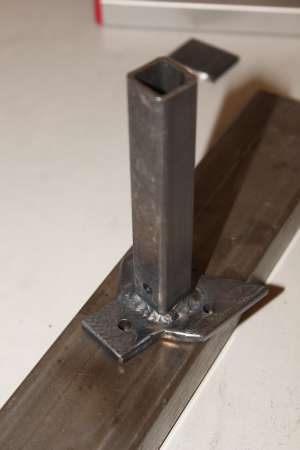
Dieses muss nun irgendwie mit dem Gabelschaft verbunden werden, muss aber noch abnehmbar sein, damit sich z.B. der Steuersatz ausbauen lässt. Das 20x20er Stahlprofil passte glücklicherweise perfekt in den Gabelschaft. Durch beides hab ich also ein 6mm Loch gebohrt, sodass eine M6 Schraube das Lenkrad vorm verdrehen sichert.
Eine Platte mit drei Löchern zum Anschrauben des Lenkrads wird an das im Gabelschaft versenkte Stahlprofil geschweisst.
Die Schrauben werden natürlich noch passen gekürzt.
Und so sieht die Lenkung dann auch schon aus.
Nun ging es daran, den Motor einzubauen und die Kette auf die passende Länge zu kürzen.
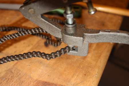
Die Stifte, die die Kettenglieder zusammenhalten, lassen sich mit dem richtigen Werkzeug einfach herausdrücken. Danach wird das Kettenschloss an die getrennte Stelle eingesetzt.
Beim Motor Einbauen musste ich darauf achten, die Kette um das Ritzel zu legen, da diese um eine der M4 Stangen, die den Motor halten, herumläuft.
Mit angelegter Kette muss diese nun noch gespannt werden. Ich hab es mal mit einer dynamischen Spannung versucht und auf beide Seiten der Motoraufhängung je zwei Federn angebracht. Leider springt die Kette so noch bei starker Belastung, ich werde es demnächst mal mit stärkeren Federn versuchen müssen.
Nachtrag: Letztendlich hab ich mich doch dazu umentschieden, den Motor nicht mit einer Feder zu spannen. Auf beiden Seiten wird eine Schraube von unten gegen die Motoraufhängung geschraubt, dadurch ist die Kette nun wirklich fest.
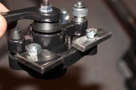
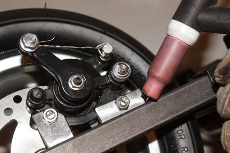
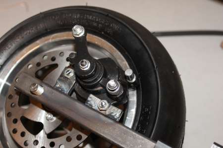
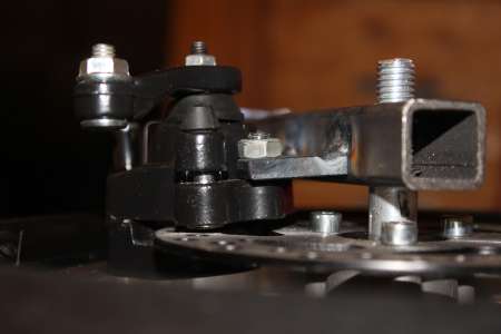
Bei einem topspeed von 50km/h ist eine Bremse sicherlich keine schlechte Idee. Die Scheibe für die Scheibenbremse ist ja bereits an der Felge angeschraubt, fehlt noch der Bremsmechanismus. Dieser hat zur Montage zwei Löcher mit M6 Gewinde. An diese hab ich zwei kleine Stücke Stahl angeschraubt und die Bremse auf die Bremsscheibe gelegt und mit einem Draht angezogen, sodass beide Bremsbacken angezogen sind.
Dann konnte ich die Stahlstücke an der Radgabel anschweissen, ohne dass sich die Bremse verzieht. Nach dem Abkühlen konnte ich die Bremse wieder lösen.
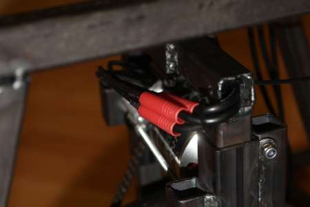
Um den Motor mit dem Controller zu verbinden hab ich drei 1m lange 12AWG Silikonkabel mit je einem 4mm Bullet Connector (die von den Lipos) versehen. Um die steifen Kabel des Motors nicht zu belasten hab ich die Silikonkabel erst mal durch die Radgabel geführt. Danach hängen die Kabel ein wenig durch und sind dann am am Rahmen befestigt wo sie die letzten centimeter bis zum Controller noch zurücklegen. Die länge ist gerade so bemessen, dass sich das Vorderrad insgesamt um 540° also 1,5 Umdrehungen drehen lässt, sodass es noch möglich sein soll, rückwärts zu fahren und dabei zu lenken.
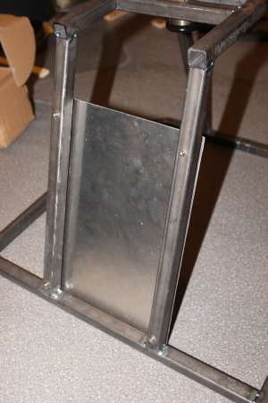
Zwischen Sitz und Vorderrad wollte ich noch ein Schutzblech haben, damit mir der ganze Dreck nicht bei voller Fahrt in die Fresse schleudert. Auch falls die Kette mal reißen sollte ist so ein Schutz zwischen Intimbereich und Antrieb sinnvoll.
An der zum Sitz hin gewandten Seite werden dann die Lipos sowie der Controller später angebracht.
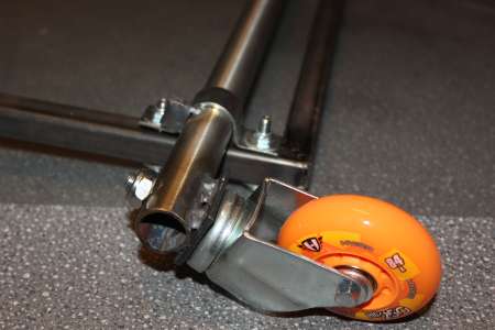
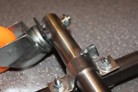
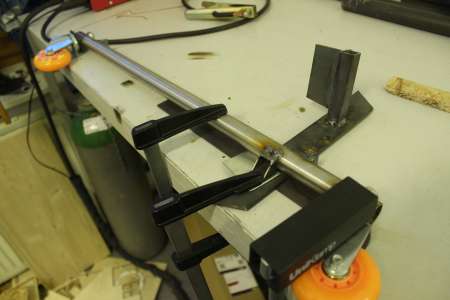
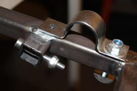
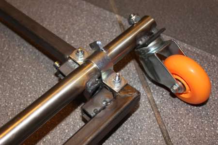
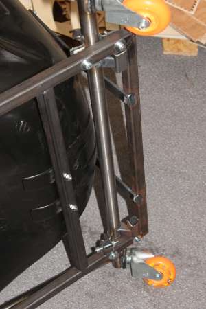
Schneller Sprung zum hinteren Teil des Carts. Die drehbaren Hinterräder werden an einem 25mm Edelstahlrohr befestigt welches wiederum durch zwei Bügel am Rahmen gehalten wird.
Damit der obere Teil vom Lager der Hinterräder stabil sitzt, muss er flach aufliegen und mit einer M10 Schraube fest angezogen werden.
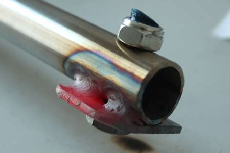
Ein kleines stück Stahl (40x40mm) ist dazu auf beiden Seiten der Achse angeschweisst.
Um das seitliche Verrutschen der Achse zu verhindern ist an beiden Seiten ein kleiner Stopper leicht angeschweisst.
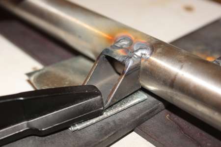
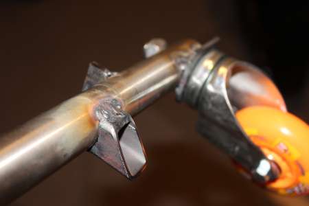
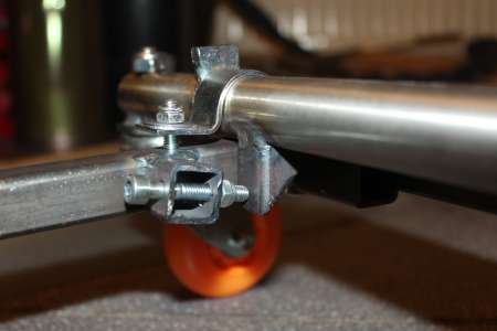
Weiterhin soll die Achse sich nur insgesamt um etwa 45° neigen können. Also von gerade bis leicht nach hinten angewinkelt.
Dazu musste noch ein 45° angeschrägtes Stahlprofil unten an die Achse.
Durch die Schraube lässt sich einstellen, wie weit die Achse drehbar sein soll, bis sie gerade steht.
Auf der anderen Seite ist erstmal ein Stahlstück grob befestigt und limitiert das nach hinten Neigen. Später hab ich links der Achse den hinteren Stopper noch hinzufügt.
Jetzt fehlt noch der Hebel für den Crazymode. Dafür hab ich das Reststück Edelstahlrohr von der Achse genommen, am hinteren Ende passend angerundet und an die Achse angeschweisst.
Sind die Räder nach hinten geneigt ist der Hebel nur wenige Grad angehoben, sodass man mit den Händen nicht auf die Straße kommt.
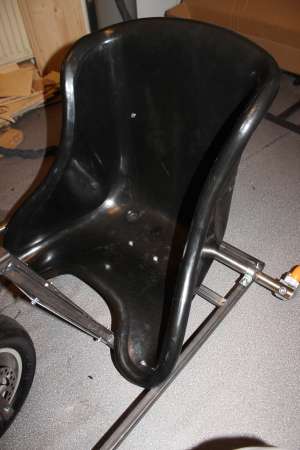
Der Sitz ist ein Kartsitzt in XXL. Naja, XXL … ich bin ja wirklich nicht dick, aber da sitzt es sich trotzdem sehr eng drin.
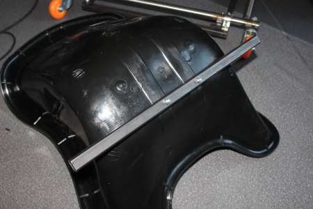
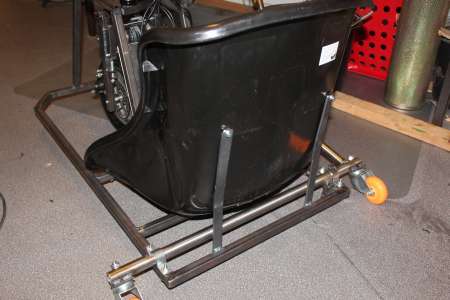
Der meiste Druck wird wohl gerade nach unten lasten, daher hab ich dort ein 20x20 Stahlprofil mittig mit M6 Schrauben durch das Plastik angeschraubt. Dann vorne zwei Löcher durch Sitzt und Rahmen gebort und angeschraubt. Erst danach konnte ich das Stahlprofil unter dem Sitzt zwischen dem Rahmen leicht nach vorne geneigt verschweissen.
Hinter dem Sitzt halten noch zwei 20x5mm Flachstahlprofile den Sitzt in Position.
Auf dem Teil zu sitzen lässt sich beschreiben wie das Fahren auf einem zu kleinen Fahrrad, da die Beine vorne stark eingezogen werden müssen.
Bis auf den Brushless Controller währe das Cart nun fahrbereit. Gut, die Bremse ist noch nicht bedienbar… aber lassen wir das.
Der BLDC Motor Controller ist ein sogenannter Mini Jasontroller.
Weblinks:
- www.etotheipiplusone.net/?p=3022
- elifebike.com wiring diagram
- etotheipiplusone.net jasontroller fansub
- yameb.blogspot.de Cruscooter and MiniJasonTroller
Vorweg: Beim Testen hab ich den Controller irgendwie kaputt bekommen, einen Mosfet und den entsprechenden Gatetreiber hats wohl erwischt. Da mir der Reperaturaufwand bei dem Preis des Controllers zu hoch erscheint habe ich einen größeren Controller geordert. Der Vollständigkeit halber möchte ich hier aber dennoch meinen Umbau beschreiben. Wen das nicht interessiert der kann direkt zum Part 2 springen.
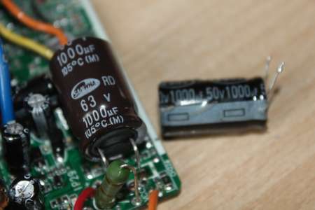
Als erstes hab ich den 50V 100uF Kondensator am Eingang durch ein 63V Äquivalent ersetzt um nicht allzusehr am Limit zu fahren.
Viele der Kabel die aus dem Controller herausragen werde ich nicht brauchen und habe diese daher ausgelötet.
Die Bedeutungen der Stecker hab ich mir anhand der oben verlinkten verkabelungsdiagramme erschlossen und bis zu den entsprechenden Pads am Controller zurückverfolgt.
Voltage Level, Cruise, EABS, Speed Limit und Pedal assisted hab ich ausgelötet und unverbunden gelassen. Three Speed kann auf einen 3-Wege Schalter gelegt oder fest verlötet werden (Low: GND mit Low verbinden, Mid: offen lassen, High: GND mit High verbinden). Brake kann später mit einem Schalter am Bremsbedal/Bremsgriff verbunden werden, damit der Motor nicht läft währen man die Bremse drückt. Throttle On/Off hab ich mit einem Schalter verbunden, damit wird dann der Controller eingeschaltet.
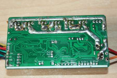
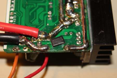
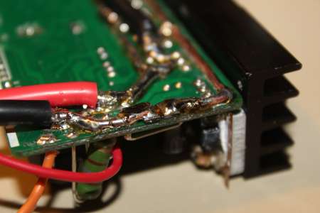
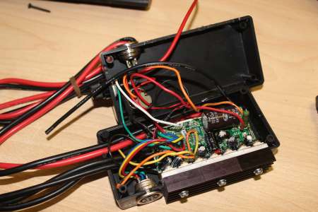
Da der controller eindeutig nicht für 2,5kW ausgelegt ist sind die Kupferbahnen entsprechend dünn. Daher hab ich die Bahnen vom Stromeingang zu den Mosfets mit Kupferdraht und Lötzinn verstärkt.
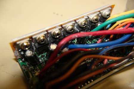
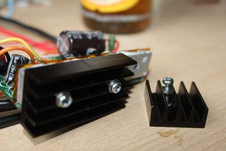
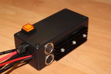
Ebenfalls muss die Hitze besser abgeführt werden, daher werden nun drei Kühler an die Metallplatte geschraubt die zuvor am Alugehäse befestigt war.
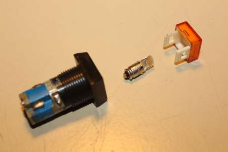
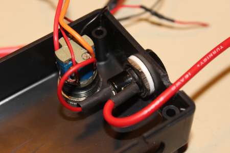
Der Schalter zum einschalten des Controllers ist ein alter Schalter mit Glühbirne als beleuchtung. Die Birne war defekt und ist eher f&uumr; >100V ausgelegt. Nachdem das Glas aus der Fassung herausoperiert war konnte eine Rote LED dort eingelötet werden.
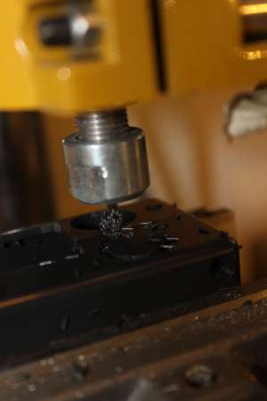
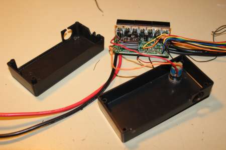
Das originale Alugehäse ist nun viel zu klein, daher kommt die Platine mit Schaltern und Buchsen nun in ein neues Plastikgehäuse.
Der 1mOhm SMD Widerstand wird unter dem 6mOhm Drahtwidershunt =P falschherum eingelötet.
Um möglichkeiten für eine Beleuchtung offen zu halten wollte ich die 50V Eingangsspannung zusätzlich aus dem Controller herausführen. Damit Kurzschlüsse etc. der eher unwichtigen Beleuchtung nicht gleich diverse Kabel durchschmoren lassen hab ich noch einen Sicherungshalter mit 1A Schmelzsicherung seitlich in das Gehäse eingelassen.
Die zwei Tuchelbuchsen dienen zum Anschluss der Hallsensoren (5 Pole) und des Gaspedals mit Bremsschalter (4 Polig).
Dann kam das Cart auf den Tisch, sodass das Vorderrad frei drehen kann. Ohne die Hallsensoren läuft der Motor wie erwartet. Bei zu viel Gas schaltet der Controller ab, da der Motor im Leerlauf die maximale Kommutierungsfrequenz des Controllers schnell erreicht. Das Anlaufen ist zudem ohne hallsensoren sehr ruckelig, da der Motor erst etwas “angestoßen” werden muss, damit der Controller die Position ermitteln kann (siehe Back-EMF (Wikipedia)).
Dann hab ich die Hallsensoren welche sich auf der kleinen Platine befinden angeschlossen. Einer der Sensoren muss sich zwischen zwei Statorwicklungen befinden, eine gute Anleitung zum Einstellen und Finden der richtigen Kombination bei e0designs.com/documentation/finding-motor-phase-sensor-combinations/.
Anscheinend war die erste Kombination die ich getestet hatte garnicht so verkehrt, der Motor drehte immerhin und das noch richtig herum, wenn auch noch so hakelig wie zuvor. Zum Gegentesten hab ich zwei der Sensoren getauscht, der Motor bliebt stehen. Da aber noch die dicken Lipos angeschlossen waren und ich wohl etwas zu viel Gas gegeben hab muss einer der Fets abgeraucht sein und seinen Gate treiber mitgenommen haben. Naja, wie bereits erwähnt hab ich mir einen neuen Controller bestellt. Getestet wird ab nun immer erst am Labornetzteil.
