Hoverbrett
Januar 2019
Nachdem das Bobbycar nun fährt wollte ich es gerne mit mehr Features, wie Lenkdifferenzial, ESP, ABS etc. ausrüsten können. Da für die vier Motoren zwei Hoverboardcontroller verbaut sind und ich ungerne an dem kritischen Teil der Software rumspiele ist mein Vorhaben, einen zentralen Controller zur Ansteuerung zu verwenden, der zu den Motorcontrollern Seriell angebunden ist.
Das Bobbycar ist jedoch eher kompakt gebaut und das Hinzubauen dieser Steuerung würde ein nahezu komplettes Zerlegen des Gefährts mit sich ziehen. Zusammen mit dem Aspekt, dass ich vieles Austesten und ggf. Umdenken muss wollte ich gerne eine einfache Platform mit der gleichen Hardware, um diese Idee einfacher austesten zu können.
Die Idee von einem Brett mit Rädern und Lenkrollen wurde bereits im “TranspOtter” umgesetzt. Wie die TranspOtter dient mein Hoverbrett am Ende auch als Platform um Dinge zu Transportieren, aber auch um Konzepte der Robotik und Regelungstechnik ausprobieren zu können.
Viel einfacher als die Aluminiumbasis eines Hoverboards, zusammen mit den Ränder/Motoren, unter ein Holzbrett zu schrauben geht es glaub ich garnicht. Zwei Lenkrollen vorne dran und fertig. Eventuell werde ich das später mal überarbeiten, aber dafür muss es erstmal fahren.


Das Mainboard des Hoverboards, welches die beiden Motortreiber enthällt, kam in das Gehäuse eines Arcor Routers. Ganz knapp waren die Elkos zu hoch, daher gucken sie jetzt aus dem Deckel heraus. Die Steuerung übernimmt ein STM32F103C “Bluepill” in einem D-Link Accesspoint Gehäuse. Zuerst hatte ich dort einen FrSky Empfänger aus dem Flugmodellbau angeschlossen, was auch funktionierte. Für den Bau einer sehr kleinen Fernsteuerung bin ich aber auf NRF24 gewechselt. Der Akku ist der aus einem Hoverboard (10S2P), der leider oben drauf musste, da unten der Boden zu nah kam.
Wie der STM32 auf dem Hoverbaordmainbaord umprogrammiert wird hab ich bereits unter “hoverboard firmware hack” beschrieben. Die Software ist hier zu finden: Github NiklasFauth/hoverboard-firmware-hack


Die angesprochene Fernsteuerung sollte so klein wie möglich werden. Auf der Suche nach einem kleinen Joystick kam ich auf die Lenovo “Nippel” (glaub sie heißen Trackpoint). Aus einem defekten Thinkpad durfe ich mir das Nippelmodul ausbauen, danke nochmal Fionera. Offensichtlich bin ich nicht der Erste, der dieses grandiose Eingabegerät weiterverwendet: Github feklee/usb-trackpoint Das Modul war nicht exakt das gleiche, das korrekte Pinout konnte ich von martin-prochnow.de übernehmen. Die Daten für x und y Auslenkungen haben jeweils 8 Bit Auflösung und werden über irgendein, vermutlich proprietäres, serielles Protokoll übertragen.


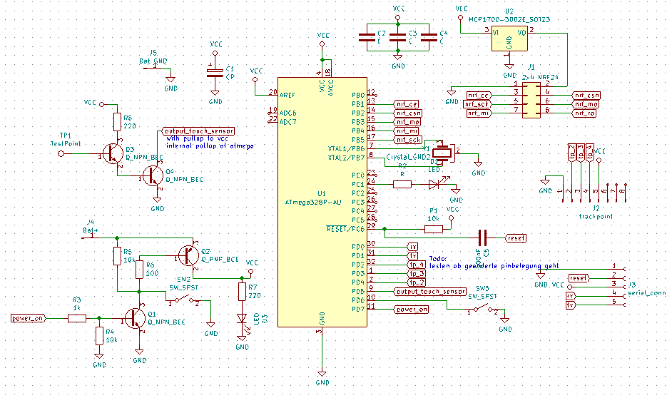
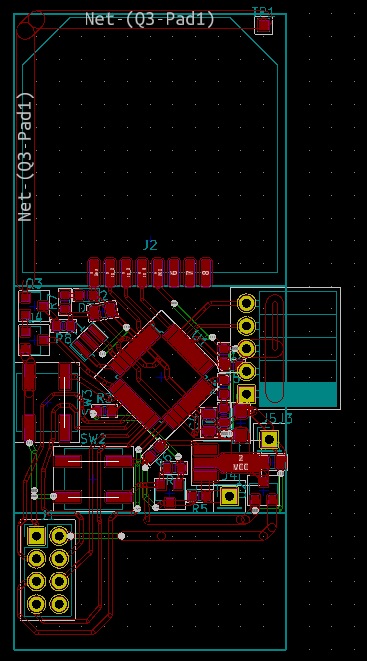
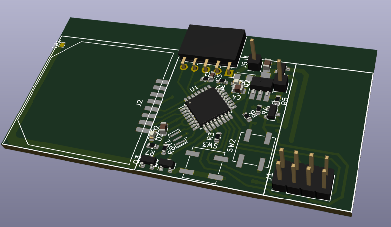
Um die Daten auszulesen und an das NRF24L01 Modul weiterzugeben hab ich einen Atmega328 mit Arduino als Pro Mini 16Mhz verwendet. Mit dessen Grundbeschaltung, einem Stromeinschalter mit Selbsthaltung (wie schon beim Belichtungsmesser verwendet) und zwei Transistoren als Berührungssensor wurde es recht knapp beim Layouten. Da ich die Platine selber ätzen wollte und die Unterseite flach bleiben sollte hab ich einige Brücken als Kupferlackdraht auf der Oberseite eingeplant. Mit ein paar Bauteilen die nicht ganz wie geplant passten ist es auch nur 10% gepfuscht.
Kupferplatinen mit Fotopositivlack selbst zu beschichten und dann zu Belichten und Ätzen ist super einfach. Doku hier: wiki.ctdo.de


Der Atmega328 brauchte noch den Arduino Bootloader, wofür ich einen Usbasp direkt an den Chip löten musste. Danach können weitere Softwareänderungen wie gewohnt seriell über die Buchsenleiste an der Seite geflasht werden. Link zum Repository unten.

Dann den Trackpoint und das NRF24 Modul angebracht. Ein 820mAh Lipo mit dem allgegenwärtigen 1S Lipolademodul kam auf die Unterseite.


Als nächstes musste ein Gehäuse um die Platine, worüber ich mir bis zu diesem Punkt noch keine großen Gedanken gemacht hatte. Ergeben hat sich eine Unterseite aus Platinenmaterial mit zwei getrennten Kupferflächen nach aussen. Diese werden dienen als Berührungssensor und erkennen, ob die Steuerung losgelassen wurde. Aus 2mm Plexiglas konnte ich mehrere Rahmenteile Lasern, die dann mit Sekundenkleber aufeinander gestapelt wurden. Mit dem Akku ganz unten und der Platine darüber kam der Deckel zum Schluss oben drauf. Dieser wird nur durch Heisskleber gehalten und kann so durch leichtes erhitzen wieder entfernt werden.


Zum Schlus hab ich die Seiten vorsichtig über den Bandschleifer gezogen und mit feinem Schleifpapier nachgeschliffen.


Die Steuerung hat vorne zwei Taster. Der Untere schaltet durch längeres Drücken die Fernsteuerung an. Der Obere dient zum Moduswechsel und als Ausschalter.
Jeder, der das Brett bisher gesteuert hat konnte bestätigen, dass es sehr intuitiv ist.

Wie kürzlich beschrieben hab ich alten Fahrrad- und Laptopzellen ein 12S6P Pack gebaut.
Das ist ein wenig größer, als die Hoverboardakkus, wesshalb ich den Router und Accesspoint aka Hoverboardmainboard und Steuerung anders platzieren musste. Auch störte es bei manchen Transportaktionen, dass die Räder höher als das Brett liegen. Durch Holzbretter als Abstandshalter zwischen Brett und Hoverboardcase entstand gleichzeitig ein perfekter Ort für das Routergehäuse.
Das Akkupack in der Bundeswehrbox wird einfach durch ein Flachstahl von unten an das Brett gedrückt und rutscht durch die vier herausstehenden Pinne, die im Brett eingelassen sind, nicht weg.
Als ich den 50V Akku das erste mal angeschlossen hab, explodierte einer der Elkos auf der Hoverboardplatine. Danach konnte ich die 50V am Ausgang des 15V Step Down Reglers messen, wo zuvor ein 25V Elko lebte.
Ich vermute der Stromverbrauch meiner zusätzlichen Steuerung und der dort vorhandenen Kapazitäten waren zu viel. Nun verwende ich einen LM2597HVS, um von den 50V direkt auf 5V zu kommen. Von dort aus geht es wie gehabt linear auf 3,3V runter.
Ein XT90 Antispark ist jetzt auch im Stromkreis zu finden und soll den Knall-Effekt reduzieren.


Gametrak
Nach dem Steuerungsprinzip der Transpotter sollte mein Brett auch ein Gametrak-Bändchen bekommen.
Für 15€ inkl. Versand hab ich einen Gametrak bei Ebay Kleinanzeigen kurzfristig bekommen. Der Gametrak war ein VR Ansatz für die PS2, bei dem zwei, aus der Bodenstation herausziehbaren, Seile an Handschuhen befestigt werden. Die Richtung wird dabei durch einen Joystickähnlichen Aufbau ermittelt, die Länge über einen Aufrollmechanismus mit Potentiometer.


Für einen Transpotter wird eine der Hälften des Gametrak zerlegt und das weiße Modul entnommen.
Nachdem die Kabelbelegung ausgemessen war, konnte dieses verlängert und mit freien ADC Eingängen des STM32F103C Microcontrollers verbunden werden.
- Braun = GND
- Grün = VCC
- Rot = Vertikal
- Orange = Länge (Eingerollt nahe VCC, Ausgerollt nahe GND)
- Gelb = Horizontal


Angebracht wird das Gametrak Modul vorne am Brett. Da das Seil meist eher Steil nach oben gehalten wird ist es vorteilhaft, das Modul etwas anzuneigen.
Mit der Ausfräsung im Holz steht das Joystick Teil nicht hervor und nimmt bei einem frontalen Crash hoffentlich keinen Schaden.


Sofern die Fernsteuerung ausgeschaltet ist, kann das Brett nun gezogen werden. Eine einfache proportionale Regelung steuert die Geschwindigkeit, ebenso wie die Lenkung.
Rücktwärtsfahren ist möglich, macht das Ausschalten jedoch schwierig.


Es muss nicht immer direkt das schwere 1/2 kWh Akkupaket sein. Ein standart Hoverboardakku passt mit etwas Schaumstoff da auch rein.
Und noch ein Anwendungszweck: Modellflugsachen transportieren.


Zeitsprung drei Jahre weiter (2022) musste das Poti des Gametrak Controlers getauscht werden. Kratzende Potis sind bei Audioanwendungen oft nervig, wenn sie aber die Geschwindigkeit eines Rollgefährtes steuern gefährlich. Gezeigt hatte sich der Defekt durch abruptes Bremsen und Beschleunigen beim Ziehen, was wich damals einen halben Kasten Bier kostete.
In der Industrie werden für Sicherheitsrelevanten Einrichtungen (Not-Aus Taster, Freigabeschalter, Quittierungstaster, Schutzeinrichtungen) oft DPDT (Double Pole Double Throw) Schalter eingesetzt. Ein Bedienelement betätigt zwei mechanisch und elektrisch unabhängige Schalter. Wichen die an der Steuerung ankommenden Signale zu stark voneinander ab oder sind sogar unterschiedlich wird ein Fehler ausgelöst.
Für den Gametrak am Brett bedeutete das für mich einen Stereopoti einzubauen und die Signale beider Schleifkontakte an zwei ADC Eingänge zu führen. Softwareseitig kann dann einerseits das Signal besser gefiltert werden, vorallem aber ein (weicher) Not-Halt bei zu starken Abweichungen der Analogwerte ausgelöst werden.

Teensy Controller
Nachdem der Gametrak jetzt etwas sicherer ist stand noch die Fernsteuerung an. Wenn über mehrere Sekunden der Nippel in die obere Rechte ecke gedrückt wurde blieben die ausgelesenen Werte “stecken”. Eher ungünstig, wenn man gerade drauf stitzt. Behoben war es mit Reduzierung der Auslesefrequenz und dementsprechender Anpassung der Sendefrequenz. Zuversichtlich wie ich war setzte ich mich drauf, fur 1-2 Minuten herum bis es mich unkontrollierbar gegen die Wand fuhr und kurz danach aus ging. Dahin war erneut mein vertrauen.
Die Zeit bis zur Abschaltung entsprach ziemlich genau der in der Hoverboardfirmware eingestellten Zeit für TIMEOUT. Das Verhalten lies sich mit Trennen des STM32 Bluepill Controllers replizieren. Mit Verdacht eines defekten LM7805 vor dem Bluepill l&oum;tete ich ihn von der Lochrasterplatine ab, wo mir auch promt eines der drei Beinchen abfiel. Aha! Wer hätte gedacht, dass ein freibaumelnder TO-220 mit Kühlkörper die Vibrationen eines Fahrzeugs nicht ewig mitmacht. Klarer Fall von Dauerprovisorium.
Beim Bobbycar war ich zuletzt auch von dem Bluepill auf einen Teensy 3.2 umgestiegen und das war nun der Anreiz das Hoverbrett folgen zu lassen. So stilvoll wie ich das Arcor Router und D-Link Accesspoint Gehäuse auch finde, diese mussten jetzt auch ersetzt werden.


Mit ein paar 3D gedruckten abstandsblöcken passt das Hoverboard Mainboard sehr gut in eine gekaufte ABS Box. Den Abstand unter der Aluplatte hab ich der Kühlung wegen gelassen. Power Knopf und die XT60 Buchse sind links angebracht. 5V vom HV Step-Down für den Teensy kommen auf der anderen Seite raus.


Nach einer späteren längeren Testfahrt wurden die Mosfets gut warm, sodass das Board ab 60 °C anfing zu piepsen. Die Temperatur wird dabei am STM gemessen. Mit der geschlossenen Box ohne Luftzirkulation war ein Abkühlen durch Warten gefühlt unmöglich.
Daher kamen zwei 5V 40mm Lüfter mit in die Box. Die Temperaturen mit aktivierter Feldschwächung bzw. Phase Advance habe ich hierbei noch nicht ausgetestet.


Um die Motorkabel vor Ästen oder Ähnlichem auf dem Boden liegenden zu Schützen kam eine PET Folie unter das Hoverboard Chassis. Die Maße habe ich mit einem blatt Papier und einem Bleistift abgepaust. Download der Zeichnung (Maß sind nicht exakt!): hoverbrett_hoverboardbase_cover.svg


Auf eine Lochrasterplatine kamen zuerst der Teensy 3.2, NRF24 sowie ein OLED Display.


Aktuellste Software und Kicad Schaltplan für Controller, Fernsteuerung und die eigenen Änderungen an der hoverboardhack-firmware: https://git.ctdo.de/interfisch/hoverbrett