Project start: December 2015
Language: German, English
CrazyCart
Part 4
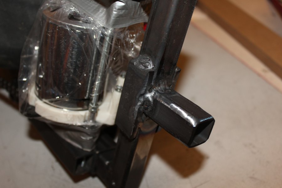
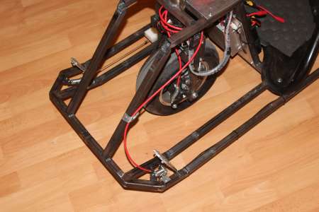
Frame extension
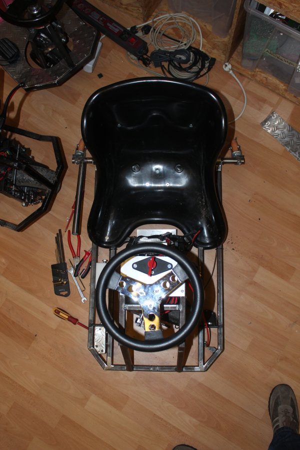
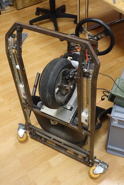
After some longer driving it got a bit painful having the knees bent so much to fit on this small vehicle.
So I decided to extend the front.(Left image is before modification)

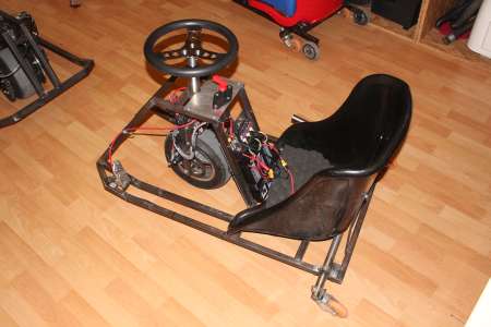
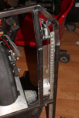
I cut all four steel sections where the pedals are mountet and welded four 10cm long steel sections in place. Those got a slight angle at one side to the front with the pedals are a bit angled up. I also moved both pedals about 2cm forward.
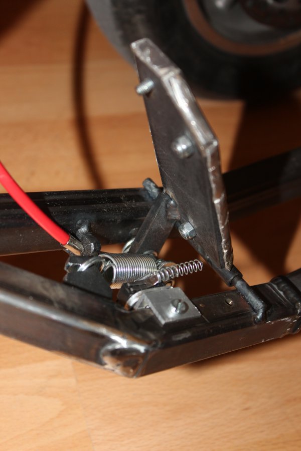
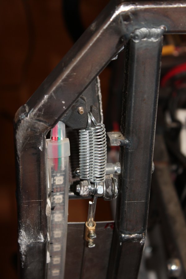
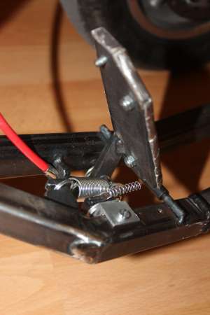
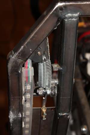
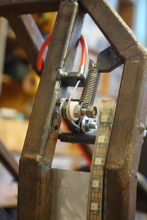
The brake switch needed a bit rethinking too, so it now gets pushed by the underside of the pedal via a spring. (Not shure if its the final version)
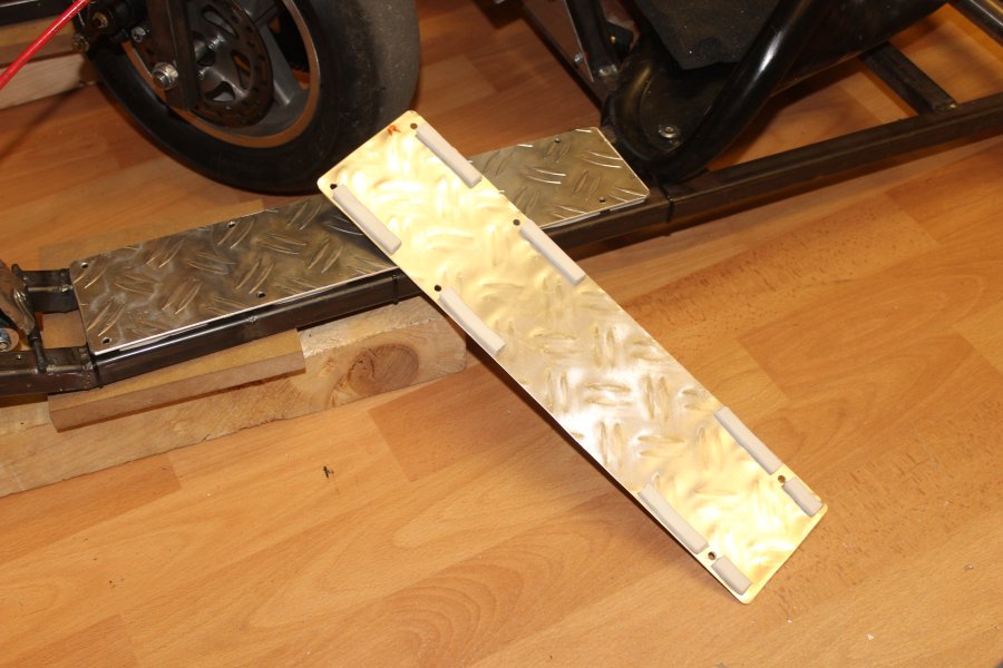
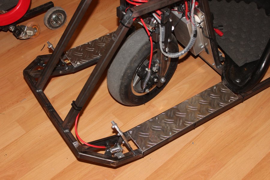
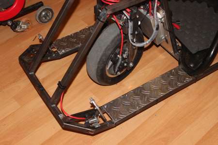
Because the front is now longer, the aluminium sheets needed to be redone. To prevent them from rattling, short pieces of foam are glued between the sheet and the steel frame.

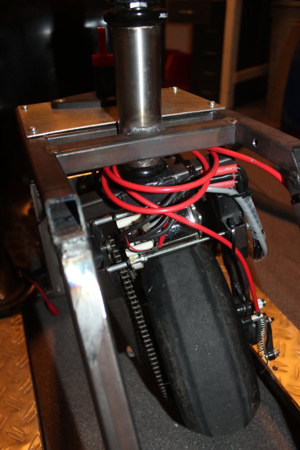
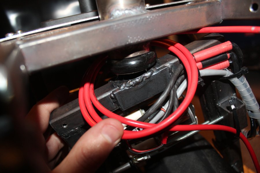
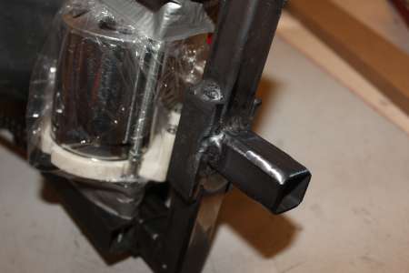
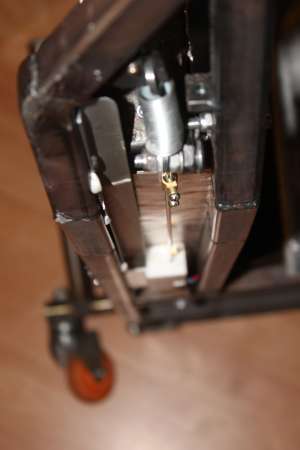
Steer Tube Repair
And then the steer tube broke off of the wheel fork. The weldseam wasn't the problem cause some part of the shaft was still in place, rather I suspect that because I turned it down in diameter for the headset, it got a bit too weak.

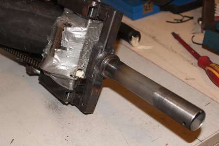
After grinding off the remnants, I welded a steel piece where the shaft goes, put the shaft over it and welded it back on with the since earned welding experience.
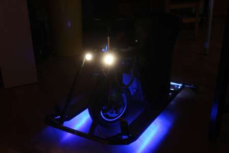
Headlights
Now it is end of december 2015 and the sun is going down quite early. So the only thing needed is light.
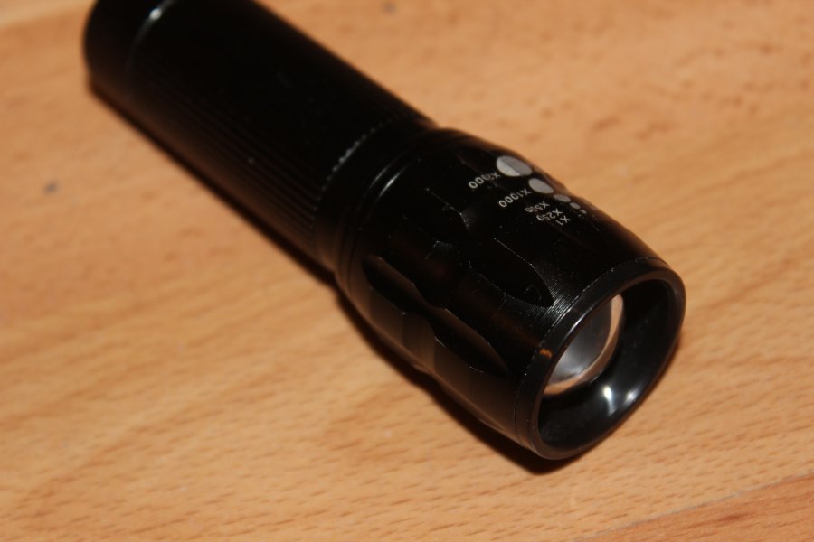
The front of the frame looks good to attach one headlight to each side.
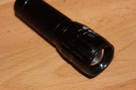
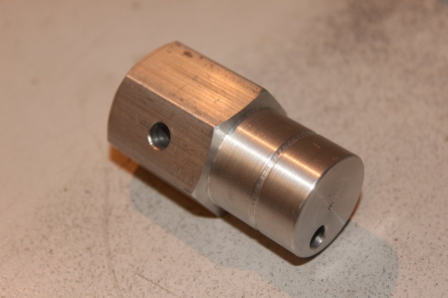
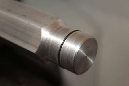
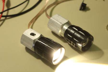
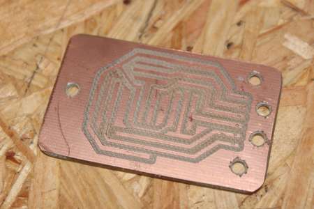
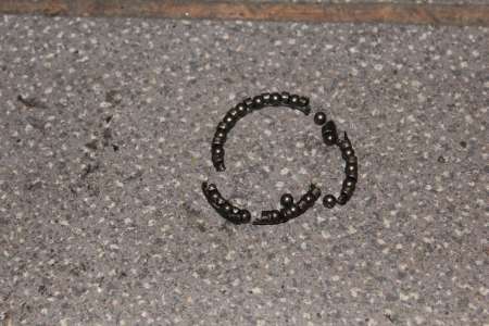
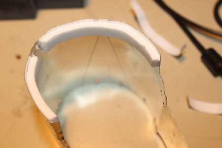
Thereto I took the front of a cheap flashlight and turned a new counterpart out of
Almulnillium.
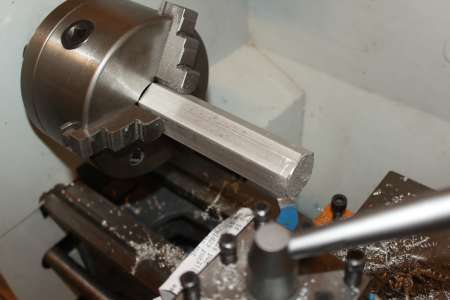
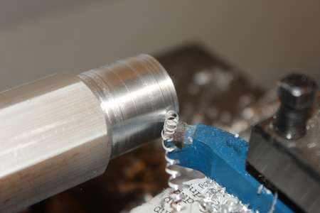
In the center of the cylindrical part a rubber ring is then embedded. With that the front Lens is able to slide back and forth like it was with the original flashlight.
The wires attached to the LED will be led through the hole on the front side. A 6mm hole on the side is there to attach the light to the cartframe.

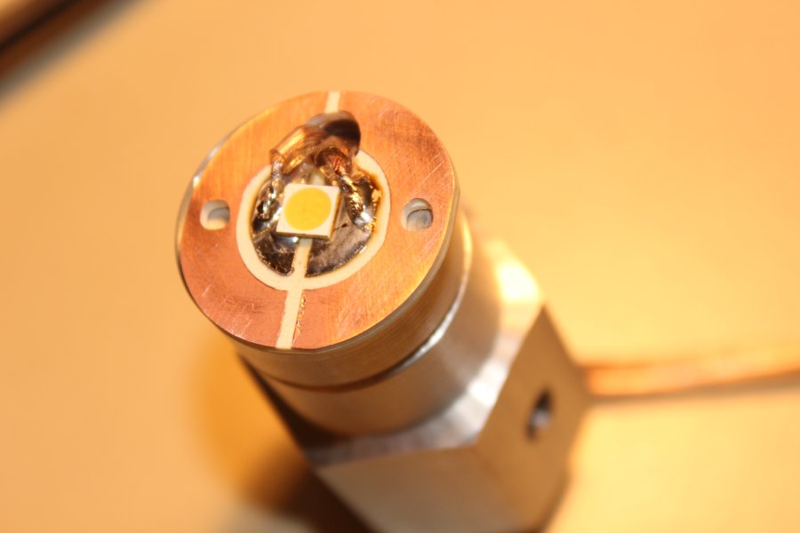
A
SMD LED OSRAM DURIS S8 GW P9LMS1.EM from Pollin with 419 lm looked good for this purpose and was quite cheap.
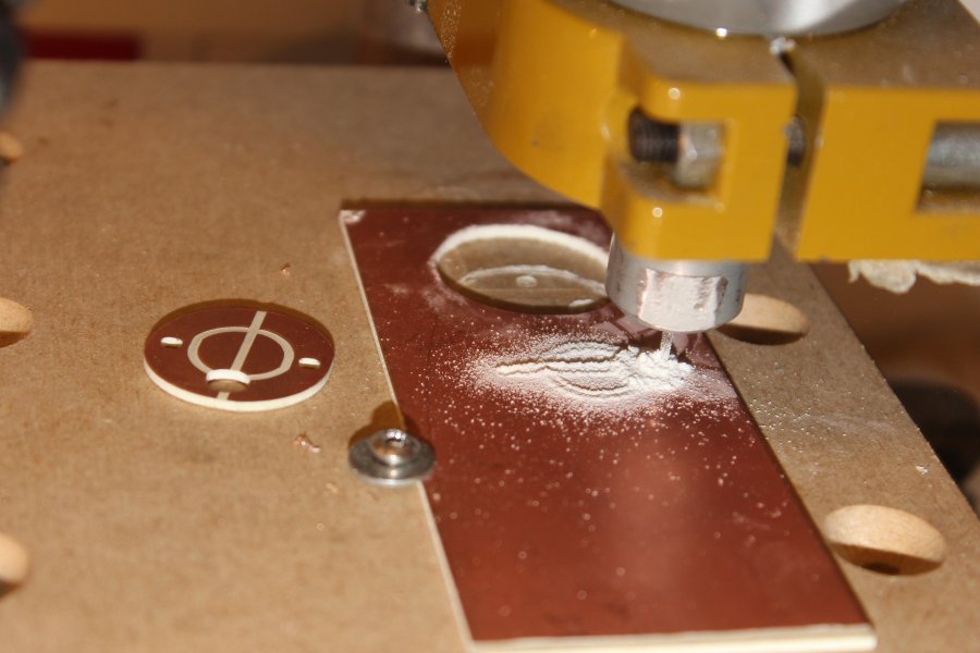
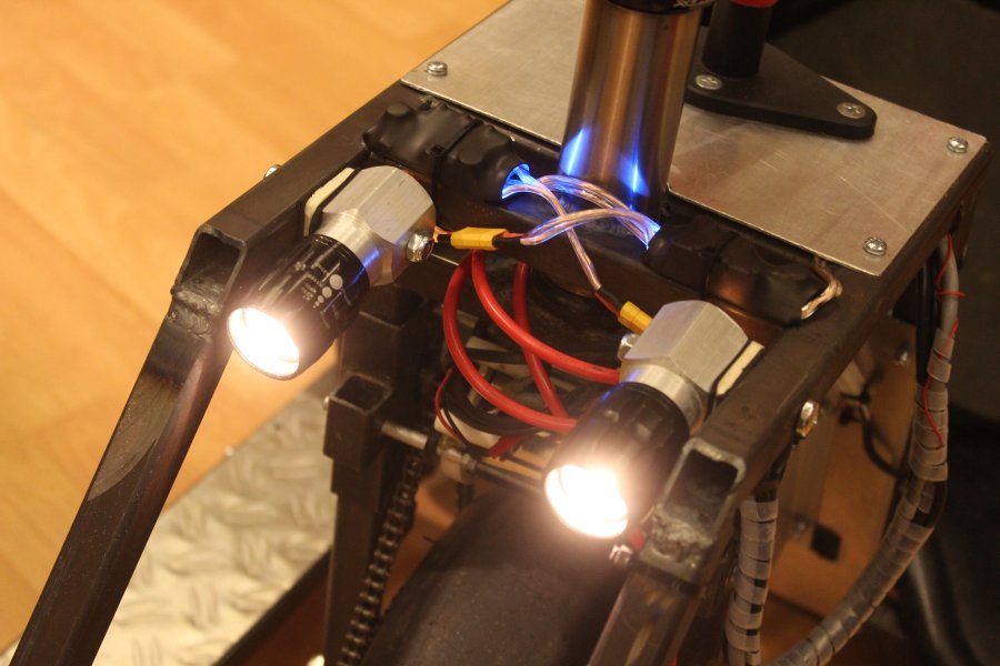
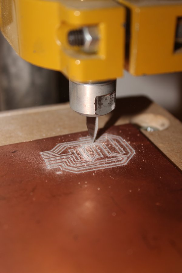
I soldered the LED to a cnc milled copper board and connected the anode and cathode to a speaker cable. With the aid of thermal compound the board is thermally connected with the Almulnilliumbody.

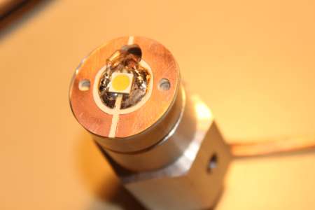
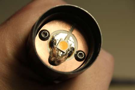
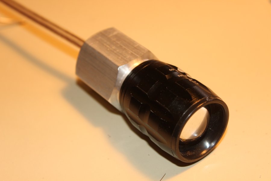
The same thing done again and the headlights are finished. At around 4W, wich the led consumes the aluminiumblock gets without active cooling around 40°C warm. Directly on the LED itself I measured up to 70°C or 80°C.

With a wooden piece and two foam rubber pieces the light is attached to the frame.
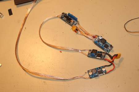
The LED's are specified for a continuous current of .2A (at around 20V). As a constant current driver I bought enough
DCDC LM2596 Step-down converter with constant current
The LM2596 as well as the input capacitor are only rated for a maximum of 36V input voltage. Because I couldn't find any constant current stepdown converter with 50V, I had to use an additional
Stepdown converter with LM2596HVS, wich first converts the 50V (=12S Lipo) down to something like 24V for the LED stepdown driver.
For testing I protected all stepdown with heatshrink tubing and attached them somewhere to the frame.
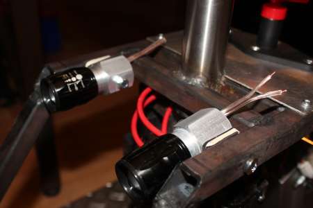
Both lights are connected with a XT30 connector to allow for an easy disassembly.
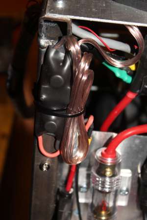
As mentioned somewhere before, all lights are fused with a 3A carfuse on the 50V rail.

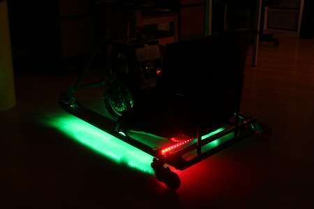
Under Cart Illumination
So, headlights are working. But there was one thing missing for the ultimate tuning. Exactly, under cart illumination.
Actually it should have been just some single color LED stripes but I couldn't decide on one color, so I took them all. I bought 5m silicone tubing waterproof WS2812 LED Stripes from Banggood for about 30 €. 2 Meters would have been enough for this cart.
Each of those 60 LED's per meter has its own controller, which makes it possible to control the color of every single RGB LED.
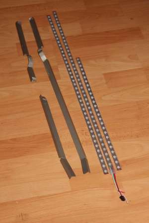
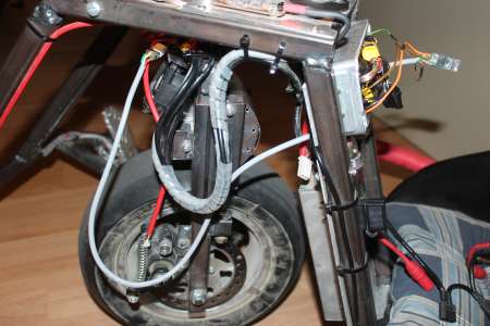
From both pedals back to the Seat I mounted some aluminium profiles under the frame, just so, that the LED's can not hit the ground.
On the front right the LED stripe gets its data and the 5V supply, which comes from a 5V Stepdown. Also a piece of ws2812 stripe is used to act as a back or brakelight right under the seat.

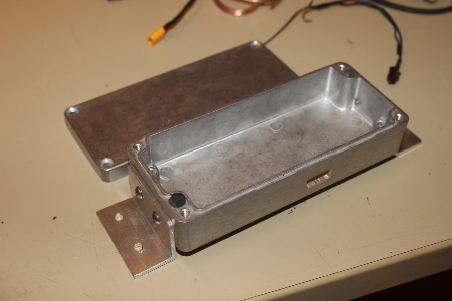
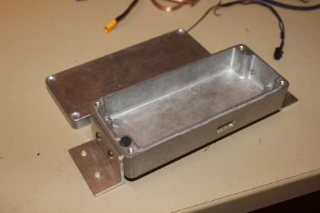
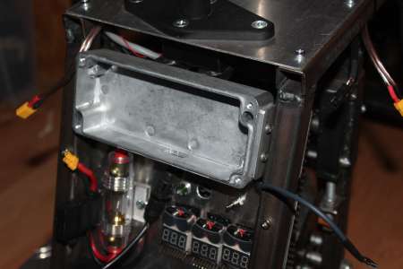
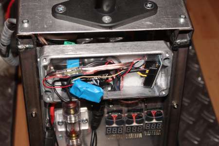
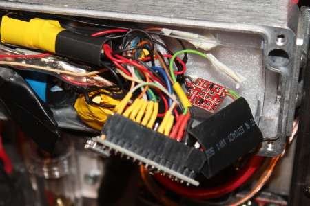
A
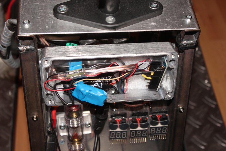
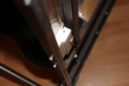
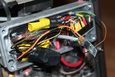
63x150x36,5 aluminiumcase is used as a housing for the two Voltage regulators (24V for the CC/CV Stepdowns for the Headlights and 5V), as well as a controller and some other electronics.
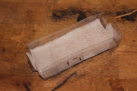
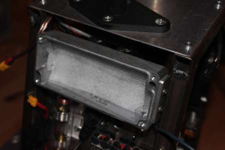
It also got some foam and plastic to prevent shortcuts to the case.
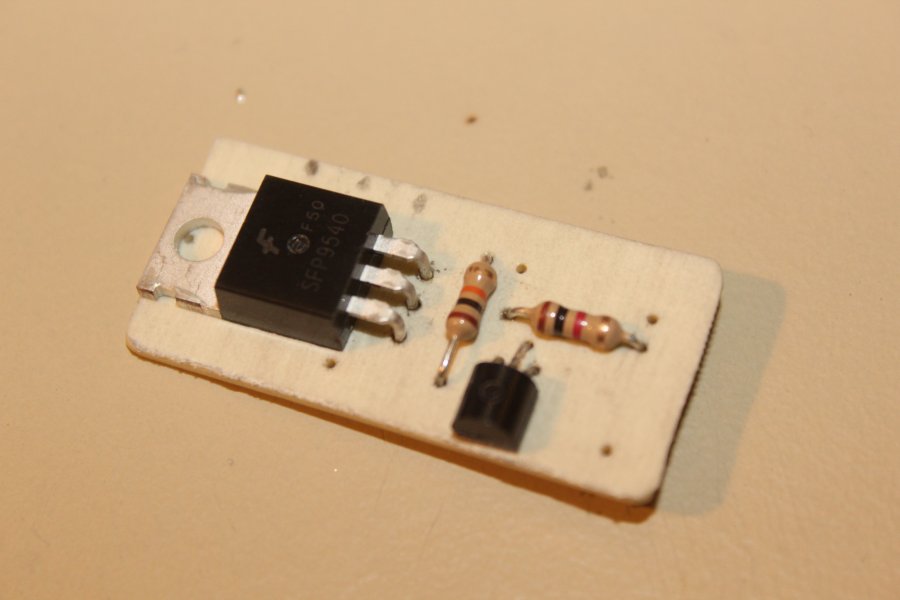
And because there will be a controller anyway, the headlights can be controlled by it too. A Mosfet is used to switch the 24V right behind the Stepdown.

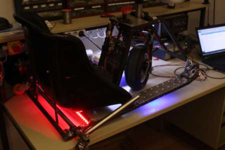
I quickly wrote a simple program for the arduino nano to control the lights, it just looks beautiful.
One thing I forgot to mention: The arduino is connected to the VESC via software (serial) and is able to read for example the ERPM and thus calculate the driving speed, so the light effects can vary with speed.
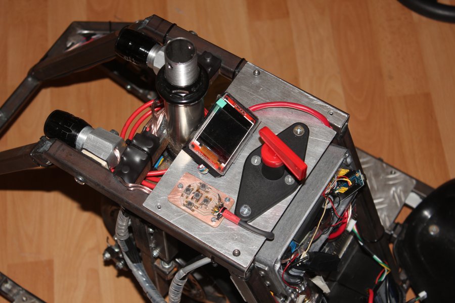
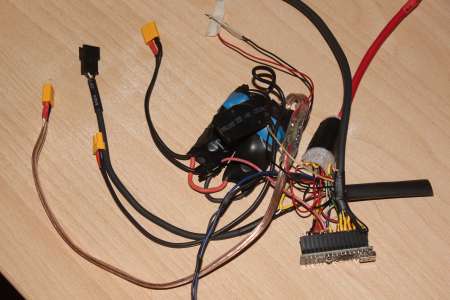
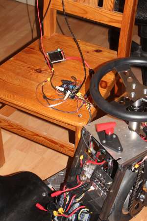
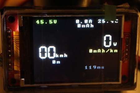
Display
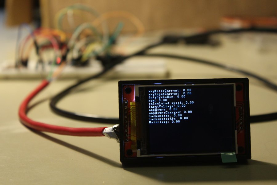
Since the arduino is now connected to the VESC and thus able to read all the data, it would be too bad to not display them somhow.
A
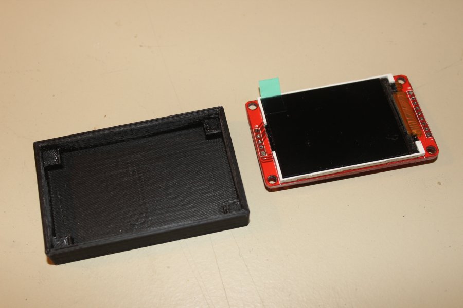
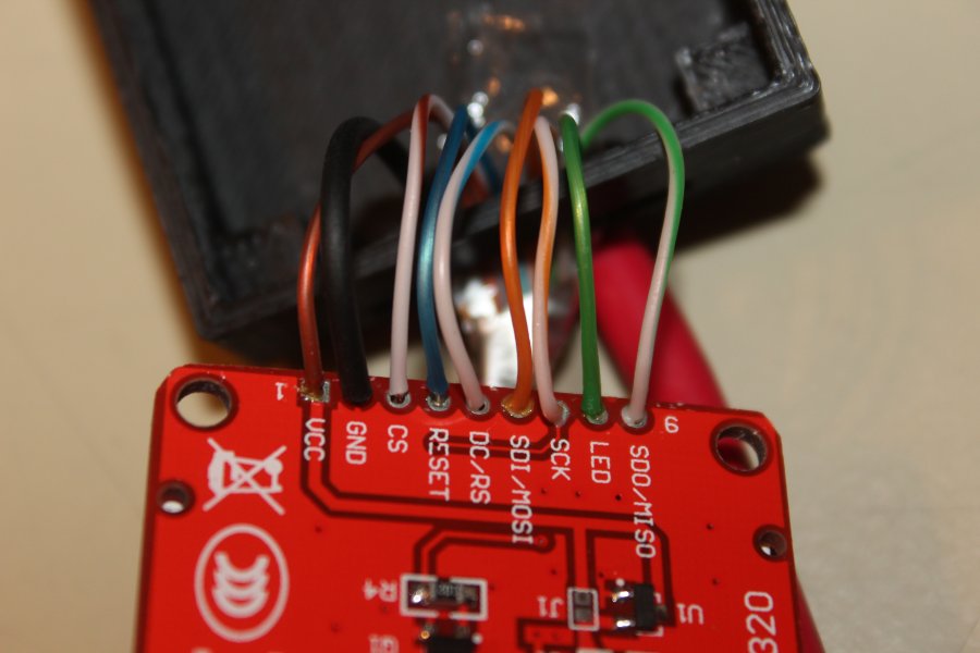
2.2" Color LCD with SPI costs only about 5 €, so I just had to use one.
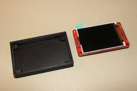
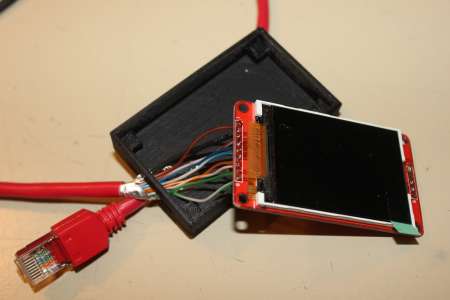
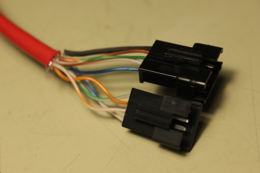
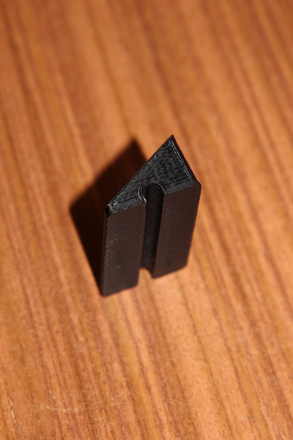
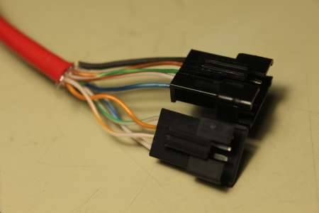
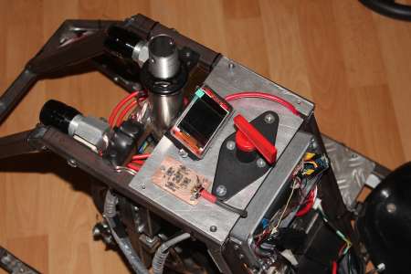
A small box was 3D-printed and a network cable was used for wiring. On the other end I attached two connectors, so the display can be taken off later.
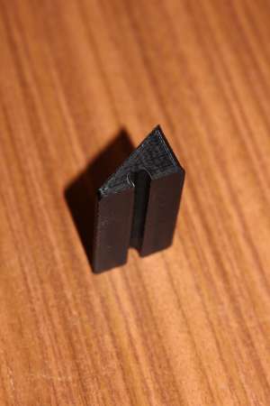
The Display needs to be at a slight angle for which I angle piece was also printed and glued to the case. It also acts as a cable guide.
STL Files:
crazycart_display_case.stl,
crazycart_display_caseholder.stl


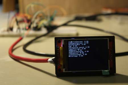
A bit more code for testing, the 32k bytes are filling up slowly.
The arduino library I used is a modified version of the
VescUartControl library by RollingGecko available at:
github.com/derlucas/VescUartControl
The display and the VESC are both working on 3.3V, so a 74HC4050 as 5V->3.3V Levelshifter was needed. The VESC is 5V tolerant, but the ILI9341 Controller of the LCD isn't and I had one input available on the 4050.
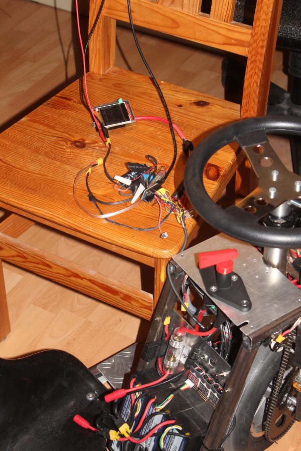
After I squeezed everything back in, it was time to do a bit more GUI programming.
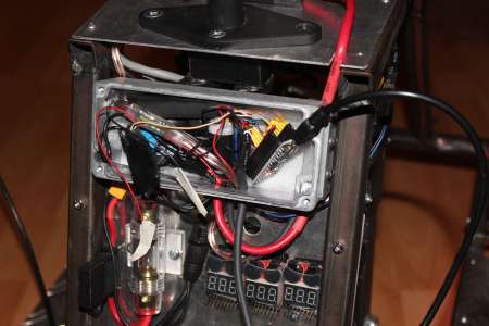
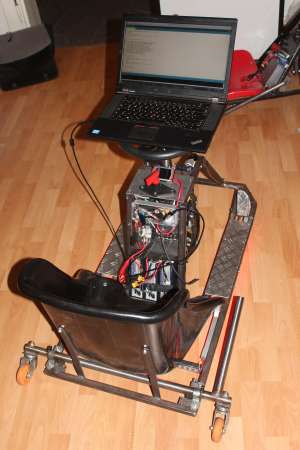
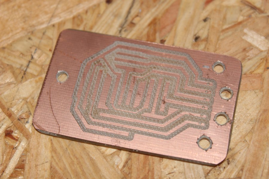
To be at least able to switch off the headlight, some sort of input panel was needed. As you can see in the following pictures, I soldered 5 Buttons to a pcb cnc routed circuit board and connected them directly to the arduino.

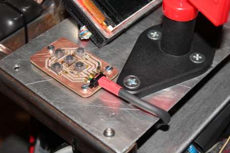
This is all the arduino was able to handle. Flash and RAM is working on its limits and every additional line of code could be too much. But all that counts is, ITS WORKING! Maybe theres the possibility that I'll exchange the arduino with a STM32 in the future.
Speaking of which: VescUartController_20160225.zip
The first time I used software serial to communicate with the VESC because hardware serial was already in use for flashing and debuggin. But soon I noticed, that the software serial has probably some timing issues because sometimes it got no new data for some seconds. Later I used a 5V-3V3 converter board to wire up the VESC to the RX and TX pins. During flashing these connections have to be disconnected.
New code: VescUartController_20160422.zip
The accelerator pedal was previously held by only one spring wich was not strong enough. After adding another one it now feels better.
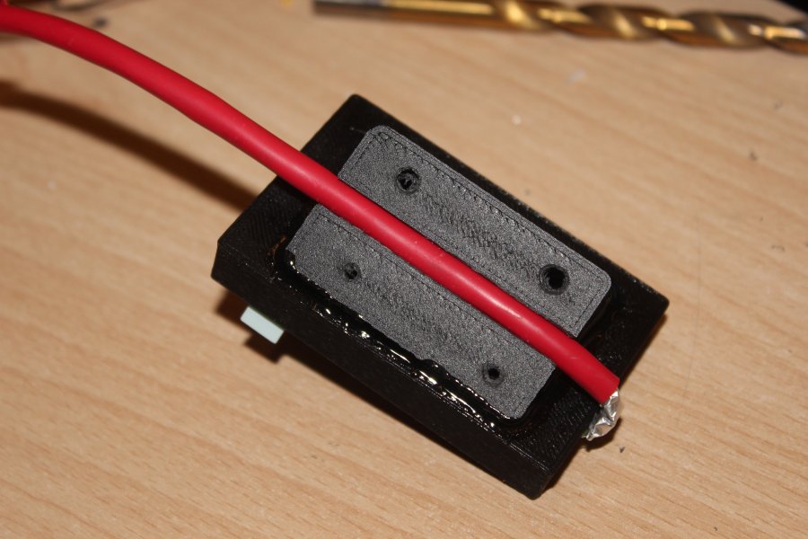
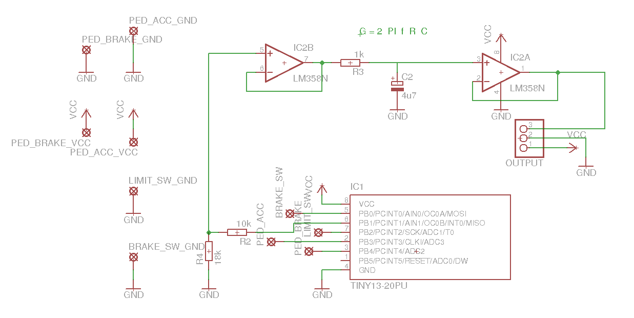
Also I removed the brake switch and replaced it with a hall sensor just like with the accelerator because the disk brake isn't as effective as the electrical one.
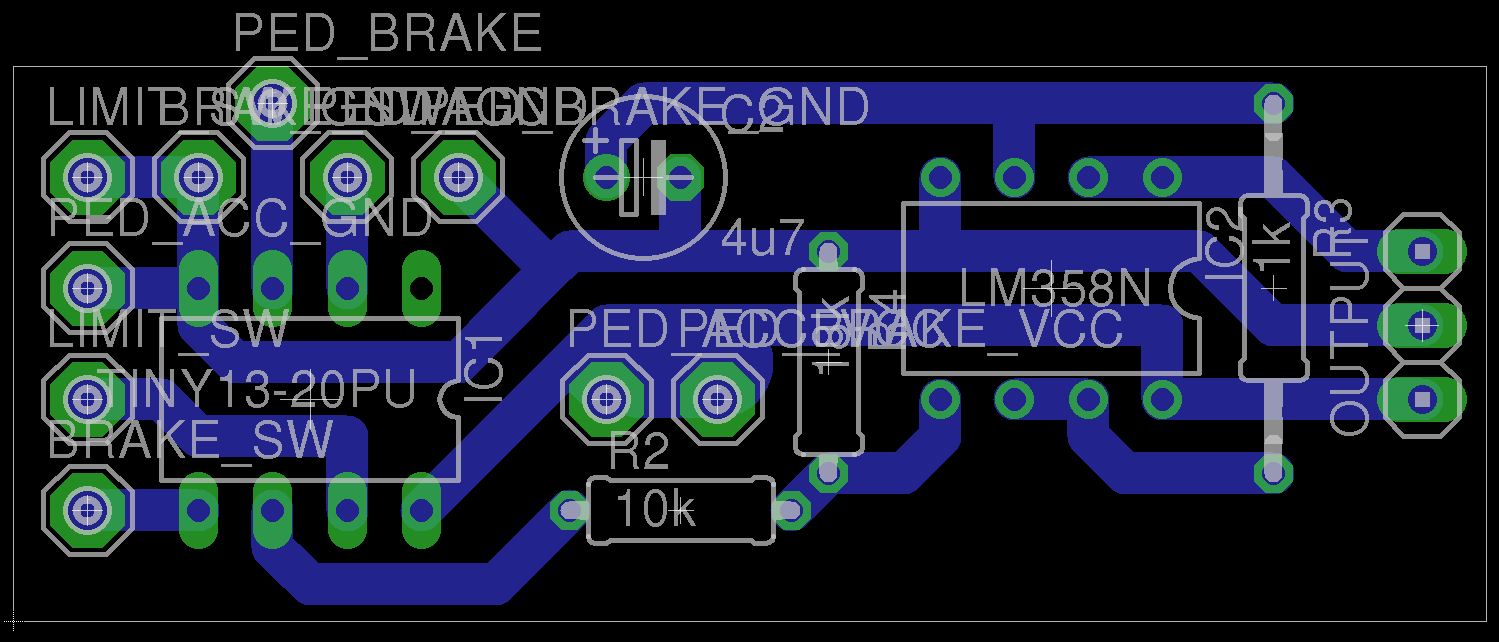
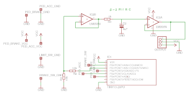
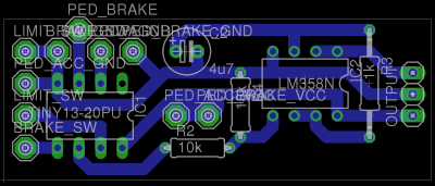
By using an hall sensor instead of a simple switch for the brake, I had to redesign the circuitboard. This was also necessary because the opamp was implemented for rail-to-rail use, wich the LM358 isn't capable of.
Attiny13 Code and Eagle Files: throttlecontroller_201605.zip
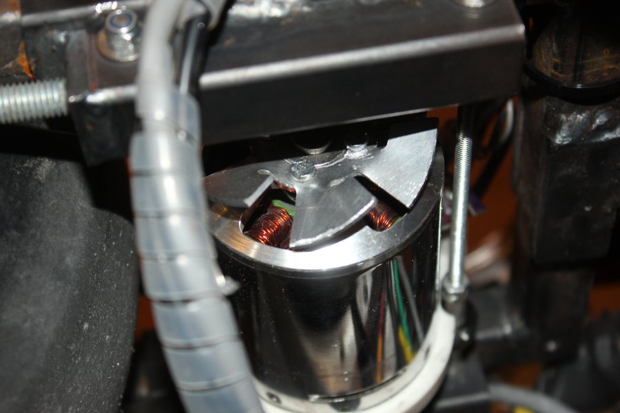
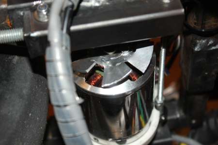
Also I noticed that the motor was getting a bit too hot with over 100 °C after about 15 minutes of rather fast driving around. Now a CNC milled fan out of aluminium sheet should help a bit with that.
14.7.2016
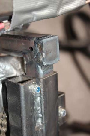
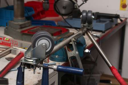
As we noticed with another cart, the upper part of the wheel fork is a weak point and can break the steel section. I dediced to close the open end of the steel section to strenghten it before is rips apart.
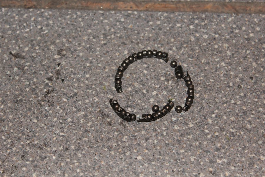
By pulling out the wheel fork to weld on it, the ball bearings of the headset (the lower part of it) fell out. Since I didn't had any replacement bearing I put them back in carefully, it works just fine although I ordered a new headset.
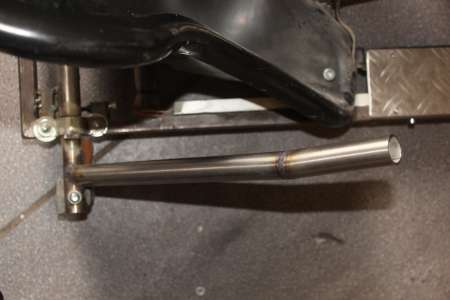
To make it easier to pull the crazymode-lever I extendet the stainless steel tube by 10 cm and welded it on at an slight angle.
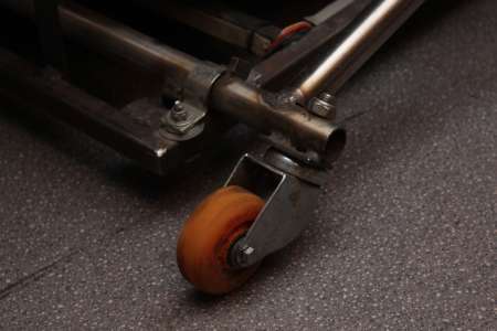
The following video was made during the same day, where you can see that the small rear wheels are also a weak point:
Breaking Wheels - CrazyCart.
Because of the rather high weight they deform quite often on those speeds and thus warm up inside until they finally are completely soft and sometimes the even explode.
I myself haven't had this happen once, but I'm also rather lightweight. An extra wheel on each side or additional straight wheels would help in this case.
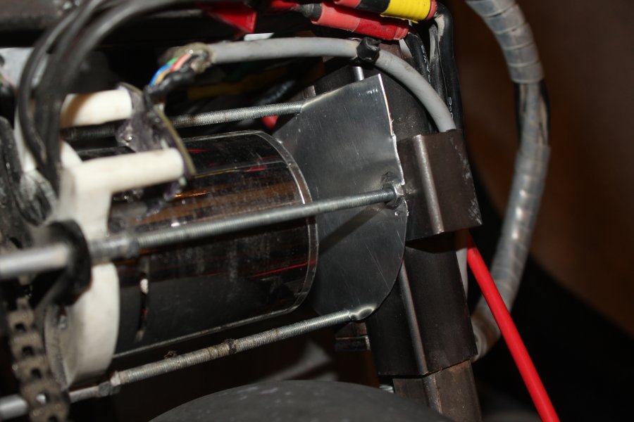
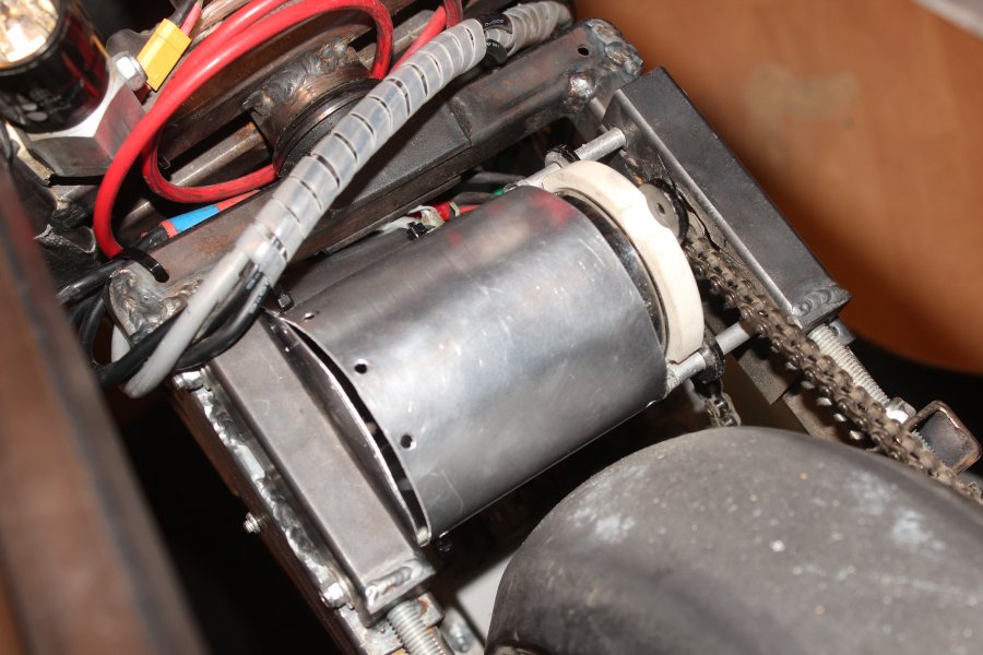
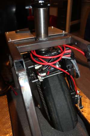
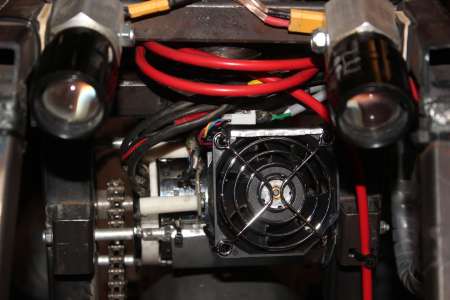
Motor Fan
As mentioned before, the motor did heat up over 100°C quite often. A few degrees more and the magnets lose their magnetism and the motor rapidly gets weaker. After 5-10 minutes of waiting everything is fine again.
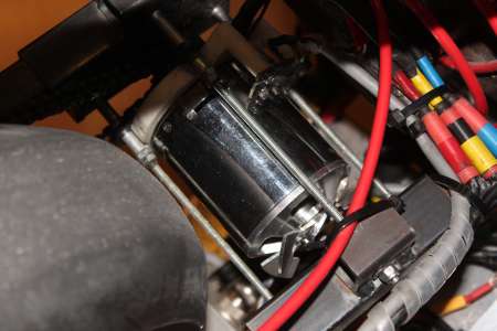
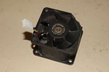
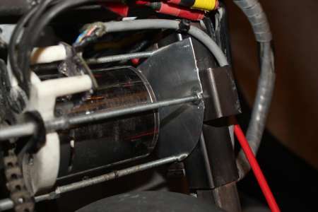
On another cart it was obviously a good idea, to put a powerful fan in front of the motor to blow air through it.
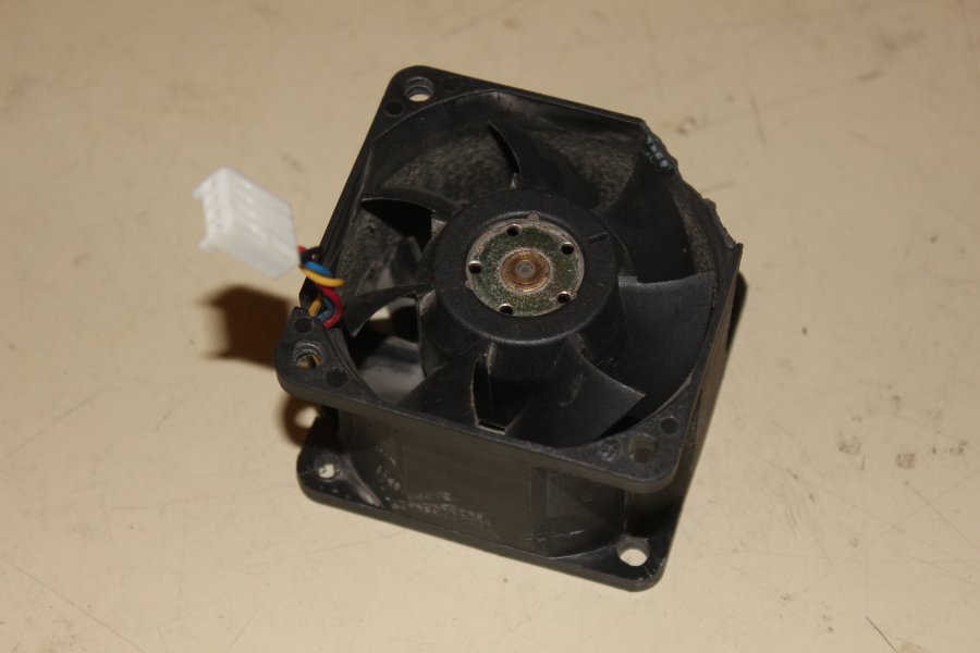
Luckily I found a 60mm server fan (Delta Electronics FFC0612DE 12V 1.2A).
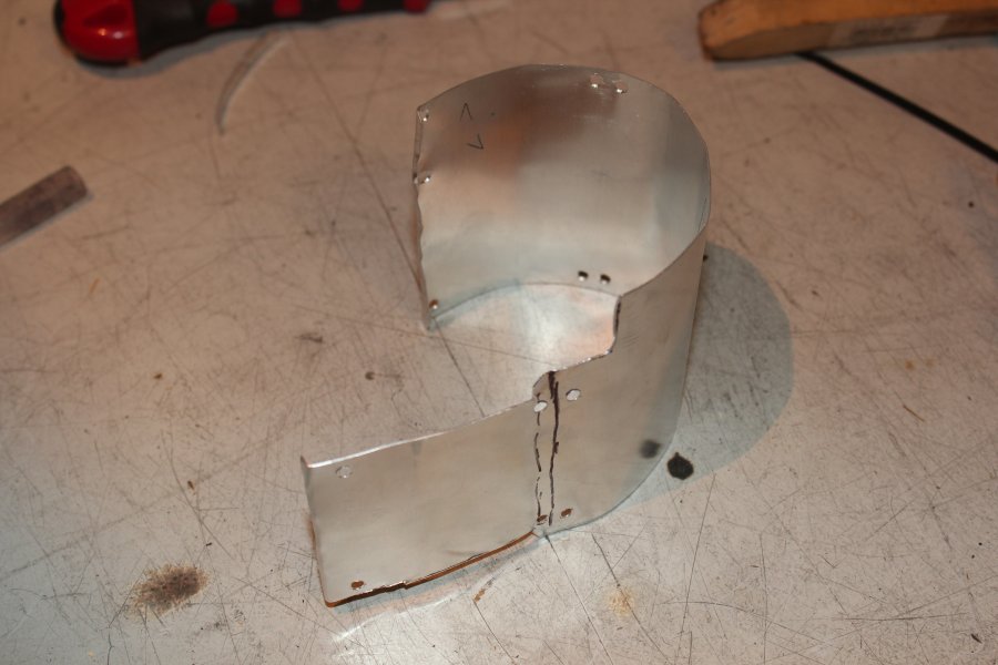
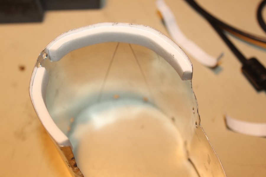
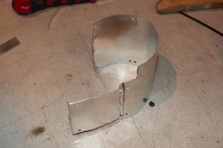
A thin aluminium sheet forces the air fo flow directly through the motor. A foam seal prevents the air from going past the rotor.
The aluminium case is held to the threaded rods by some zip ties.


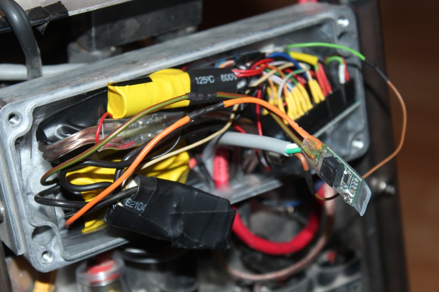
In the, somewhat crammed, controllerbox were only a 24V and 5V stepdown "installed". However, the fan needs 12V so another Stepdown from 24V->12V needed to be put in.
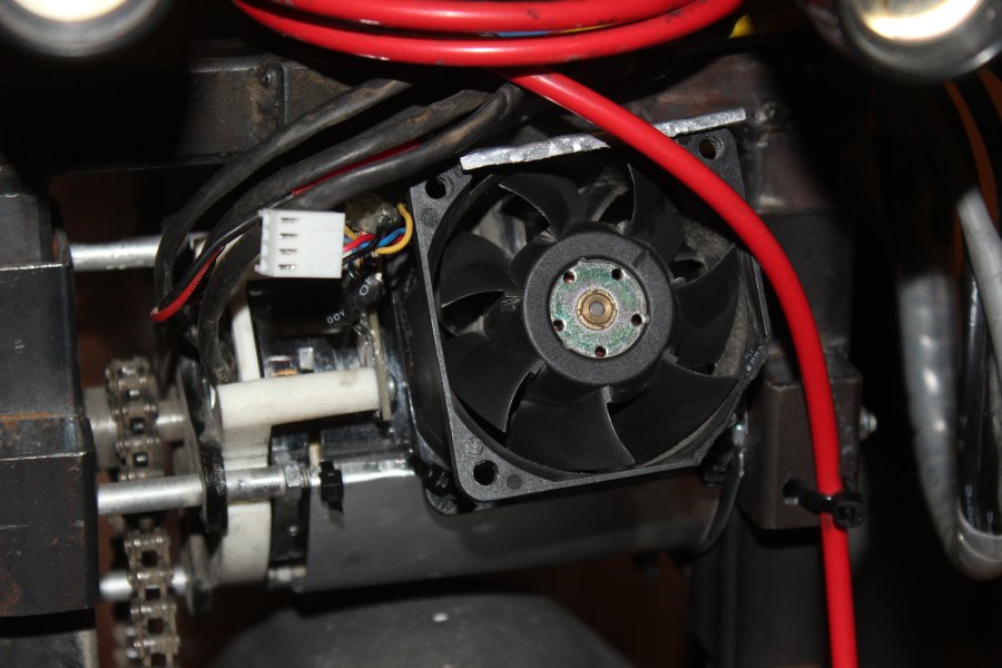
The fan has a 4 pole connector, ground, 12V, speed output and pwm-in. The pwm input was great to control over the arduino. The fan isn't silent, by any means.
Finally a protective grille was added in front of the deadly spinning thing. Haven't tried to put my finger in and I won't.
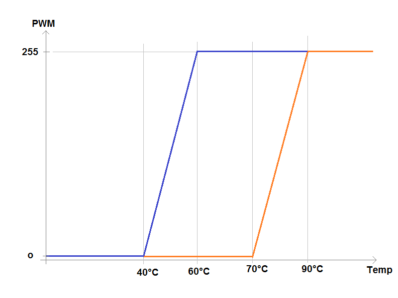
The fan speed is controlled by the measured temperature inside the motor. A simple linear controller from temperature to pwm value was to primitive, in my opinion, because the fan doesn't keep cooling the motor down after it has been very hot, for example during a break.
The sketch shows the controlling concept I used, which uses some kind of hysteresis. Here, the fan starts spinning not until 70°C and reaches it's maximum speed at 90°C. If then the temperature drops the fan keeps its speed until the temperature drops at least below 60°C and falls to 0 at 40°C.
So much for theory! We'll see if it works.
Edit: It works, but I had to add some smoothing filter in software for the temperature readings.
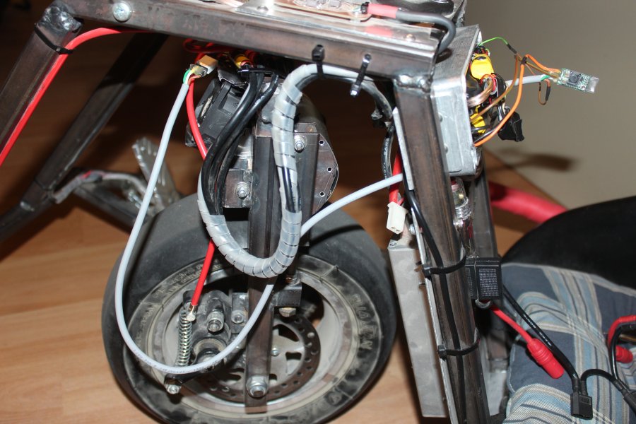
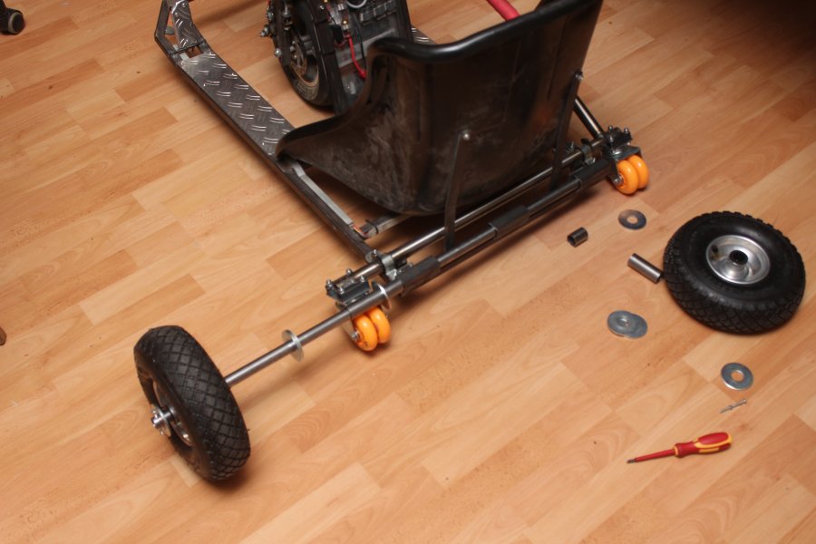
Rear wheel upgrade
Still running my first set of rear wheels after 2 years. But since they are rather worn down and on the other carts those wheels got destroyed pretty often even if they are of good quality, I'm going to switch to two wheels on each side.
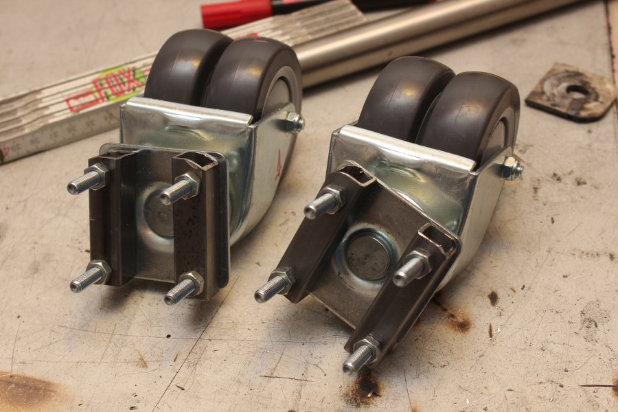
The new wheel holders are quite a bit wider and needed a different way of mounting.
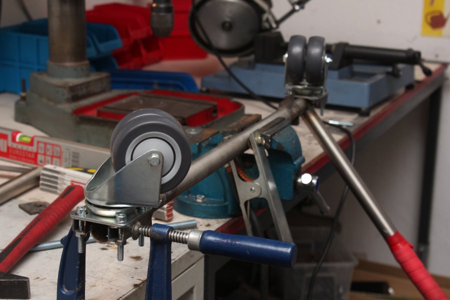
Two small pieces of square steel tubes were mounted to the four existing holes by first aligning them to the steel rod, then drilling the holes for the M6 screws.
With the help of a level, I was able to rotate both wheel holders so they are parallel to each other. Afterwards they got welded together.

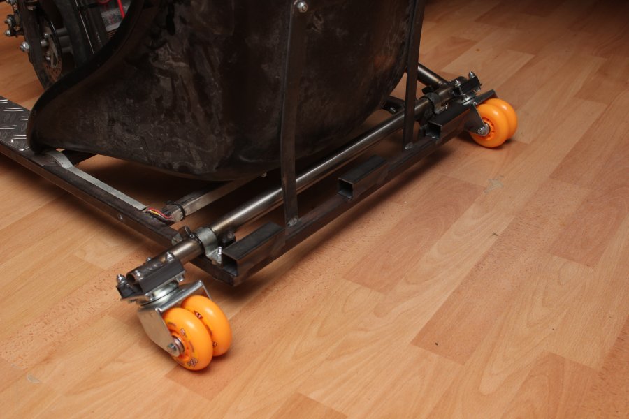
After that, a whole set of Hyper Pro 250 skate wheels (72mm 84A) was installed.


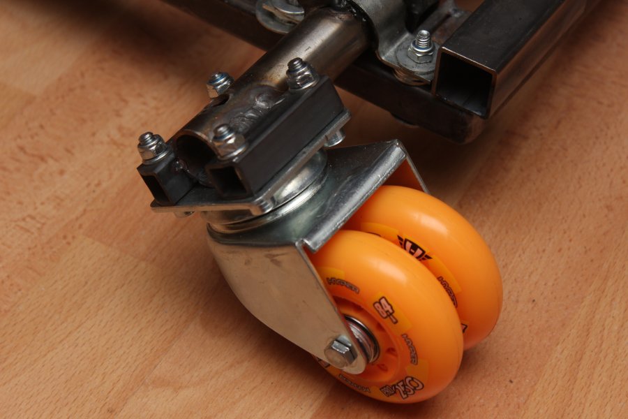
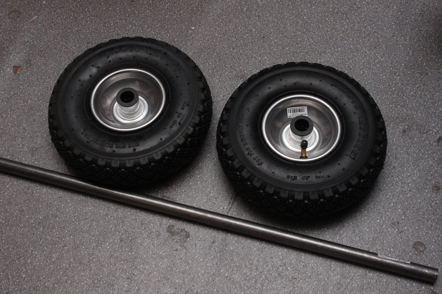
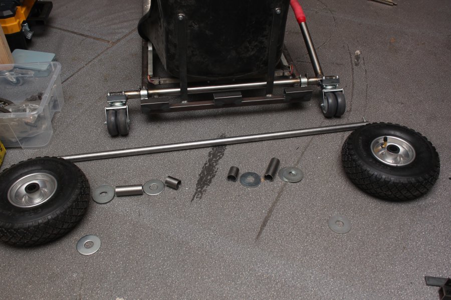
Even with doubled amount of rear wheels the cart is still not really able to drive off road. So I purchased two tires (each 12€) and a 1m long steelrod with 20mm in diameter where the needle-roller bearings are going to ride on. These wheels should be big enough to enable me to drive on grass or similar gounds.
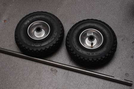
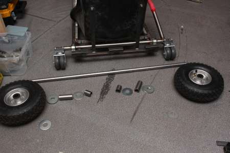
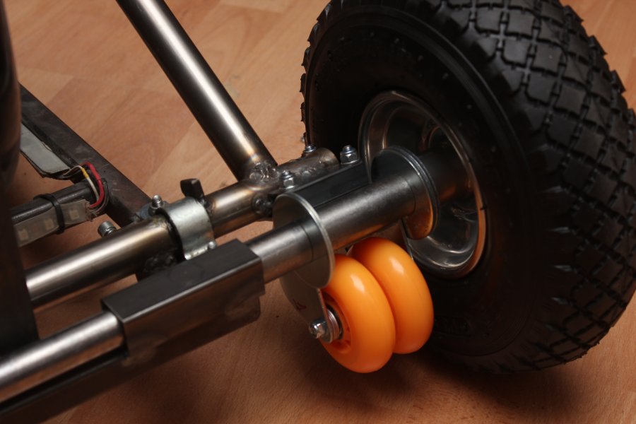
The tube gets pushed through three square steel profile pieces which are welded to the rear of the cart frame. Multiple spacers made out of bigger steeltubes and some big washers help keeping the tires at their positions and also lock the smaller wheels in position.
On both ends M4 screws or cotters keep the wheels on the axle. For dissasembly it is sufficient to remove those from one side and slide the whole axle out to the other side.


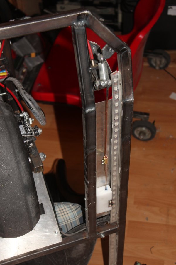
Throttle and brake pedal fix
I have already had to repair the cable for the disc brake several times, as it had torn off due to the frequent bending.
As an improvement, I thought about bending the cable around a small pulley so that no lateral forces occur at the attachment point.
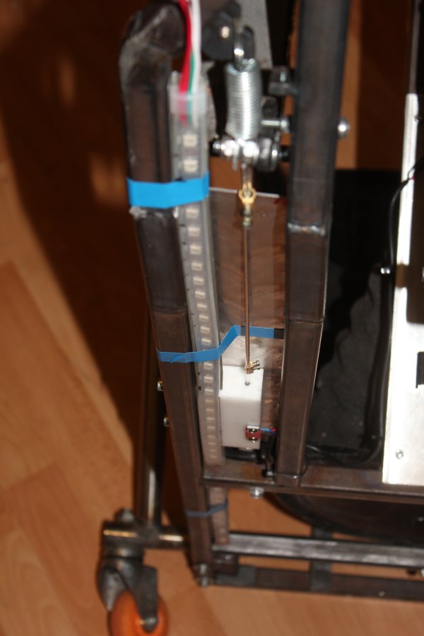
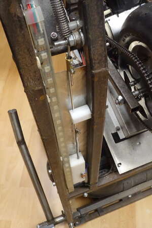
On the accelerator pedal, the rod to the Hall sensor is relatively long and therefore bends quite easily. As an optimization, it is now inserted through a POM block as a guide in the middle.
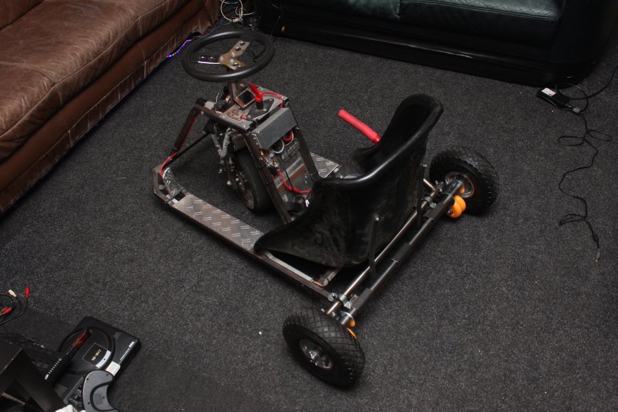
After these small fixes and pumping up the wheel, the Crazycart continues to work well in 2024.
 Part 1