CrazyCart VESC
Oktober 2015
Inhaltsverzeichnis
Wie in Part 2 bereits erläutert, war auch der zweite Controller (Greentime) nicht für meinen Anwendungsfall geeignet.
Auf der suche nach ESC Nummer drei sind wir dann über das VESC gestoßen, ein Open Source und Hardware Speed Controller primär für E-Longboards entwickelt.
Mit Features wie 120A (Peak), Software zum Einstellen aller Parameter per USB und Regenerativen Bremsen, um nur einige wenige zu nennen. Der Preis liegt beim Selbstbau um die 80 Euro.
Zum Zeitpunkt der Bestellung war Hardware Version 4.7 aktuell. Das Board ist verglichen mit den ganzen Chinacontrollern sehr klein, was das zusammenlöten nicht unbedingt einfacher macht. Gerade der Treiberchip (DRV8302) machte wegen seiner Massefläche auf der Unterseite schwierigkeiten beim Löten. Eine Heißluftlötstation mit Heizbett ist hierbei unabdingbar.
Die Mosfets hingegen liessen sich ganz einfach mit einem dicken Dachrinnenlötkolben großflächig aufbraten.


Nachdem alle Einzelteile drauf waren, musste der STM noch geflasht werden. Dazu verweise ich mal einfach auf die Anleitung: vedder.se/2015/01/vesc-open-source-esc/


Leider ist an der Platine für meinen Geschmack etwas zu viel an Größe gespart worden, sodass es sich beschissen befestigen lässt. Um es aber nicht einfach nur in ein Gehäuse zu setzen, sondern die Wärme von den Mosfets auch abtransportieren zu können, fräste ich aus einem Alublock einen Bügel, der mit Wärmeleitpads von oben die Fets an das Alugehäuse presst.


Hier noch das angesprochene Fischer Aluminiumgehäuse von Reichelt: DPL 1-1, KOH-1160, KOL 1/160 ME


Die 8 AWG Silikonkabel wirken hier tatsächlich etwas überdimensioniert.


Möglichst nah am ESC sind dann noch zwei 1000uF 63V Elkos ans Kabel angelötet.


In eine der Blenden kamen dann noch ein paar Löcher und Schlitze für (von links nach rechts) Stromkabel, Mini USB Einbaubuchse, Diverse Schalter und Kabel, Tuchelbuchse f. Hallsensoren, Motorkabel.


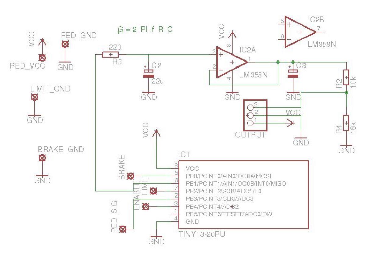
Leider hatte das VESC in Version 4.7 noch keinen zweiten ADC Eingang um den Bremsschalter mit anzuschließen. Daher hab ich wie auch schon zuvor einen Attiny 13 genommen, welcher Gaspedal und Bremsschalter zu einem Analogsignal vereint. Dadurch ist der Normalzustand (kein Gas, keine Bremse) bei 50%, was im BLDC-Tool einstellt werden kann. Da der Attiny auf 5V läft, der ADC aber mit 3.3V arbeitet war ein Spannungsteiler R2, R4 hinter dem Opamp, welcher als Tiefpassfilter des PWM Signals dient, nötig.
Hier noch Schaltplan und Code des Attiny: throttlecontroller_20151115.zip
Edit 22.4.2016: Die Schaltung funktioniert so nicht richtig. Der LM358 ist kein Rail-to-Rail Opamp, wesshalb er wie dargestellt bei nur 5V Versorgungsspannung nicht funktioniert. Der Spannungsteiler R2, R4 muss also direkt am Ausgang des Attiny, gefolgt von einem ersten Puffer. Die bessere Schaltung ist irgendwo hier zu finden.
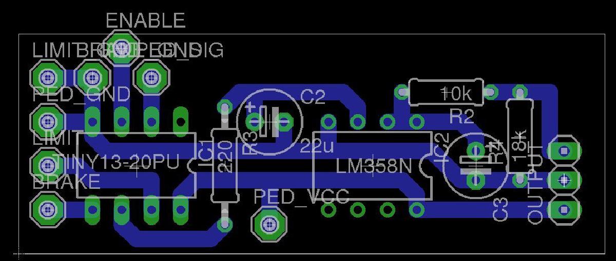
Ganz so geil ist das PCB gefräste nicht geworden, ging aber schnell und funktioniert.


Und so konnte ich den neuen Controller dann endlich wieder einbauen. Die Löcher für die Kabel wurden später noch mit Silikon abgedichtet.


Leider hat das ESC nicht die möglichkeit eines Ein/Aus Schalters wie z.B. der Greentime controller. Ein Notaus Schalter empfinde ich aber dennoch als Pflicht für ein Gefährt mit der Leistung, wesswegen ich einen “Natoknochen” (oder auch (Batterie-)Trennschalter) direkt zwischen ESC und Pluspol eingebaut hab. Dieser dient aufgrund des fehlenden Antispark nicht als normaler Ein/Aus Schalter, sondern soll nur im Notfall betätigt werden.


Und so war es dann endlich wieder fahrbereit. An den Einstellungen für das VESC musste und werde ich wohl noch etwas weiter Einstellen müssen.

