CrazyCart Pedale, Controller und Motor
Juli 2015
Inhaltsverzeichnis
- CrazyCart
- Pedale, Controller und Motor
- VESC
- Rahmen, Licht, Display und Räder
Pedale
Bremse sowie das Gas sollen per Pedal betätigt werden. Bremse links, Gas rechts. Die Pedale werden mit jeweils einem Bowdenzug verbunden.
Beginnen wir mit der Bremse: Der Bowdenzug (roter Schlauch) kommt von der Schreibenbremse und wird 2 1/2 mal um den Gabelschaft gewickelt. Dadurch kann das Vorderrad je 270° nach links und rechts bewegt werden, der Bowdenzug wickelt sich dann einfach etwas ab bzw zusammen ohne irgendwo hängen zu bleiben.

An das vordere Ende des Rahmens kommen die Pedale. Um diese auch irgendwo zu befestigen und um die Füße irgendwo abzustellen musste noch links und rechts ein Stahlprofil dazu. Damit der Sitz danach noch reinpasst hab ich diesen etwas zurechtgesägt.


Nun zu den Pedalen. An ein Stahlrohr (9mm Aussendurchmesser, 7mm Innen) kam ein recht breites Flachstahlstück in Form eines Pedals. Unten dran noch ein Hebel, der nachher das Stahlseil vom Bowdenzug ziehen soll. Damit der Bowdenzug auch die benötigen ~2cm Zugweg hat wird dieses etwa 3cm vom Drehpunk des Pedals angebracht. Das Pedal dreht sich insgesamt um etwa 45°, rein rechnerisch hätte man damit dann einen Weg von 2,12cm. Das Rohr wird dann auf ein Stück 6mm Rundstahl geschoben und dieses am Rahmen etwas angeschweisst.


Das Pedal soll sich selbstständig aufrichten und auch etwas mehr Druck dem Fuß entgegensetzen. Daher ist am Pedal sowie an der Bremse selbst eine Feder angebracht. Eine Schraube, die Seitlich im Rahmen steckt, begrenzt den oberen Pedalwinkel.


Um die Füße abzustellen und der Optik halber bekommen die Pedale und der Boden ein Aluminium Riffelblech.


Für; das Gas wird eine Spannung von etwa 1V bis 4V am Controller erwartet. Aus einem Handgas hab ich den Hallsensor ausgebaut, ein SS49E.
Damit dieser eine Spannung von 1 bis 4V ausgibt muss ein Magnet vom Süd bis Nordpol an ihm vorbeigeführt werden. Dazu hab ich in einen POM Block ein für den Magnet passendes 7cm langes Loch gebohrt in welches der 15mm lange Magnet von einer Seite hinein geschoben wird. Eine Druckfeder und eine M10 Stellschraube halten den Magnet mit den hinteren Ende am Hallsensor. Von vorne wird eine 2,5mm dicke Aluminiumstange eingeschoben und drückt den Magneten bis zu 15mm hinein, wodurch die Spannung von 1V auf 4V in etwa steigt.


Der weisse Block POM kam anschließend unter das Fussblech und wurde mittels Lüsterklemmen zum Einstellen mit dem Hebel des Pedals verbunden.


Die E-Bike Controller haben meist die Funktion, das Gas zu blockieren wenn gebremst wird. Dazu muss ein Schalter an der Bremse mit dem Controller verbunden werden.
Ich hab dazu einen Mikroswitch unterm Bremspedal angeschraubt. Ein gebogenes Blech unterm Pedal drückt den Switch normalerweise. Tritt man das Pedal etwas wird der Taster losgelassen. Die Kabel zum Controller sind mit dem Switch als “Normally Open” (NO) verbunden.


Kleiner Zeitsprung: So hab ich es dann etwas später angepasst. Ein gebogenes Stück dicker Kabelbinder drückt beim Treten des Pedals von oben den Mikroswitch herunter. Die Lösung mit dem Metallblech war nicht zuverlässig genug.

Da der Mini Jasontroller zuletzt aufgegeben hatte hab ich mir diesmal einen etwas Größeren zugelegt. Einen “GREENTIME 15 Mosfets 48-84V 1500W 45Amax Dual mode Sensor/Sensorless Brushless DC Motor Controller”. Angegeben ist ein Current Limit von 45A, was bei 50V ja dann 2,25kW währen, .. mal sehn.


Dieses eine Exemplar hat sich wohl durch die QC gemogelt, falls es überhaupt eine gab. Naja, der Händler hat einen zum Austausch geschickt. Da diese Controller aber wohl zu funktionieren scheint werde ich ihn erstmal verwenden.


Um den Controller und die Sensorlernfunktion zu Testen wurde der Controller an zwei in Reihe geschalteten 24V 50A Servernetzteile angeschlossen. Im Gegensatz zu Lipos limitieren diese den maximalen Strom, falls doch irgendwas sehr schief läuft.
Die Sensoren werden so auf der Motorglocke platziert, das einer von ihnen zwischen zwei Statorwicklungen liegt. Dann werden die beiden weißen Kabel zusammengesteckt (“Learn Wire”) und der Controller eingeschaltet. Kurz danach fängt der Motor sich hoffentlich an zu drehen. Nach etwa 2 Sekunden wird der Controller wieder ausgeschaltet/vom Strom getrennt. Nun hat der Controller die Sensor/Motor kombination gelernt. Falls der Motor sich falschrum gedreht hat muss der Lernvorgang wiederholt werden. Danach sollte man nicht vergessen die weissen Strippies wieder zu trennen.
Das Einlernen umfasst nicht die genaue Ausrichtung der Sensoren, das muss immernoch selber ausprobiert werden.
Das gute an dem Greentime Controller ist, dass er wie auch der Mini Jasontroller ab einer gewissen Drehzahl in den Sensorless betrieb schaltet.

Hier wieder die Belegung auf dem PCB.

Die unnötigen Kabel wie Cruise und Regen. Braking hab ich direkt am Board ausgelötet. Wie es auch schon beim anderen Controller geplant war werden die Sensoren über einen 5 Poligen Tuchelstecker angeschlossen. Für die Tuchelbuchse hab ich im Controllergehäuse ein passendes Loch gebohrt und die Tuchelbuchse dort eingebaut. Um zu sehen was der Controller so macht kamen noch zwei Kabel für die Status LED dazu. Den “Cycle Analyst” hab ich nicht enfernt, da dort ein paar interessante Daten vom Controller rausfallen, wie z.B. ein Hallsignal (für ein Tacho) oder der Spannungsabfall am Shunt (für den fließenden Strom).


Der Grund warum ich beim Testen des Controllers strombegrenzte Netzteile statt der Lipos verwendet habe ist Sicherheit vor zu hohen Stromflüssen, die die Lipos zum Brennen bringen können. Gerade hinsichtlich der Positionierung der drei Akkus am Cart entschied ich mich für eine 60A AGU Sicherung wie sie auch im Car Hifi eingesetzt werden.
Der Kabelbaum vom Controller ist nun etwas aufgeräumter. An den Motorkabeln hängt ein MT60 Stecker, die “Iginition” hat einen Killswitch bekommen und “Three Speed” einen drei Wege switch. “Three Speed” konnte ich leider nicht fest auf High verlöten, da nur im Low Speed Modus der Motor einigermassen smooth anläuft.
Links neben der AGU Sicherung befindet sich ein Flachsicherungshalter, in welchen später eine kleine Sicherung kommt welche die Beleuchtung absichert.


Da der SK3 Motor eher für den Betrieb in einem Flugmodell mit ordentlich Luftzug von vorne ausgelegt ist bekommt er hier eher weniger kühlende Luft ab. Das Lüfterblatt hab ich flach 2mm hoch aus PLA 3D gedruckt und anschließend die Blätter mit Heißluft erwärmt und angewinkelt.


Dann gings nach draußen zum Testen. Das Gaspedal ist sehr leicht zu treten, sodass der Fuß beim beschleunigen etwas zurück geht und somit das Kart wieder langsamer wird und so weiter. Neben dem nötigen hall sensor tuning bemerkte ich, dass der Motor nach nur 5-10 minuten langsamen rumfahren (20km/h) schon sehr heiß wurde. Kommt warscheinlich vom hohen Übersetzungsverhältniss (11 zu 78), dem großen Reifen (28cm Durchmesser) und dem schnellen Motor mit 192 KV.
Die Rechnung ergibt eine maximale Geschwindigkeit von 71,5km/h (28cmPi 11/78 * 50V* 192KV) was ebenso eine ineffizienz bei geringen Drehzahlen bedeutet.
In Hinblick auf die Gleichung ist es wohl am besten die “umdrehungen pro minute pro Volt” (KV) des Motors zu verringern, anstatt den Raddurchmesser oder die Übersetzung zu ändern da vorne eh schon wenig Platz ist.
Nachdem der Sprengring vom Shaft entfernt und die vier Schrauben am unteren Ende der Glocke gelöst sind spannt man den Stator am besten mit etwas Holz in einen Schraubstock ein und zieht die Glocke gerade nach oben weg.


Der Motor ist mit 15 Parallelen 0,4mm Kupferlackdrähten 7 mal pro Anker als dLRK gewickelt (=14 Turn). Das ergibt einen nachgemessenen Innenwiderstand von 30 mOhm pro Phase und laut Angabe 192KV.
Es half nichts, das ganze Kupfer musste Runter. Ein paar Stunden später sah der Stator etwas leer aus.


Um mehr KV zu bekommen müssen mehr Wicklungen auf das Eisen. Laut Berechnungen passen 9,5 Wicklungen pro Stator bzw 19 Turns pro Pol für die Angestrebten 100KV bis 150KV ganz gut. Nachdem die Anzahl der Windungen feststand konnte ich mit dem drivecalc ausrechnen, wieviel und wieviele Kupferlackdrahtstrippen ich parallel nehmen muss bei gegebener Drahtdicke von 0,65mm. Ich habe mich für 4 Parallel entschieden, damit das Ganze nicht zu knapp wird.
Gewickelt habe ich nach dem dLRK Evolution Schema siehe bavaria-direct.co.za, bei welchem die Enden die zusammen verbunden werden müssen direkt nebeneinander herausgeführt sind.
Das Schwierigste beim Wickeln war, mit den Gedanken nicht abzudriften und sich zu verzählen.


Unzähliche Stunden später war der Motor fertig gewickelt.


Ein NTC, welchen ich noch mit eingeklebt hab soll später Aufschluss über die Kerntemperatur des Motors geben. Damit die Drähte nicht verrutschen und sich an der Motorglocke verhaken hab ich diese mit ein wenig zwei Komponenten Epoxy gesichert.


Um die neue KV des Motors zu ermitteln kann dieser in einer Drehbank eingespannt werden. Die Leerlaufspannung über eine Phase kann mit einem Oszilloskop gemessen werden. Aus der Frequenz des Sinus (hier 124Hz) kann die Drehzahl des Testaufbaus ermittelt werden (124Hz * 14Pole / 2=868 rpm). Dazu braucht man noch die RMS Leerlaufspannung (hier 4,8V). Nach der Colin-Dedman-Formel (rpm/(Vrms * sqrt(2) * 0,95)) komme ich also für meinen Motor auf 135KV, was durchaus dem gewünschten Wert entspricht.
Erste Fahrtests zeigten auch einen geringeren Motorstrom pro Phase von 9A bei 10km/h, vorher über 15A.

Der Motor ist nun umgewickelt, trotzdem ist das Problem des Stotterns bei hohen Strömen geblieben.
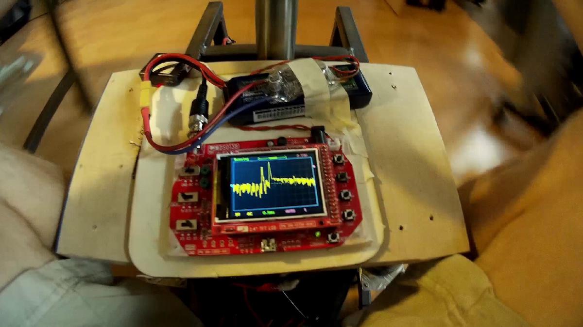
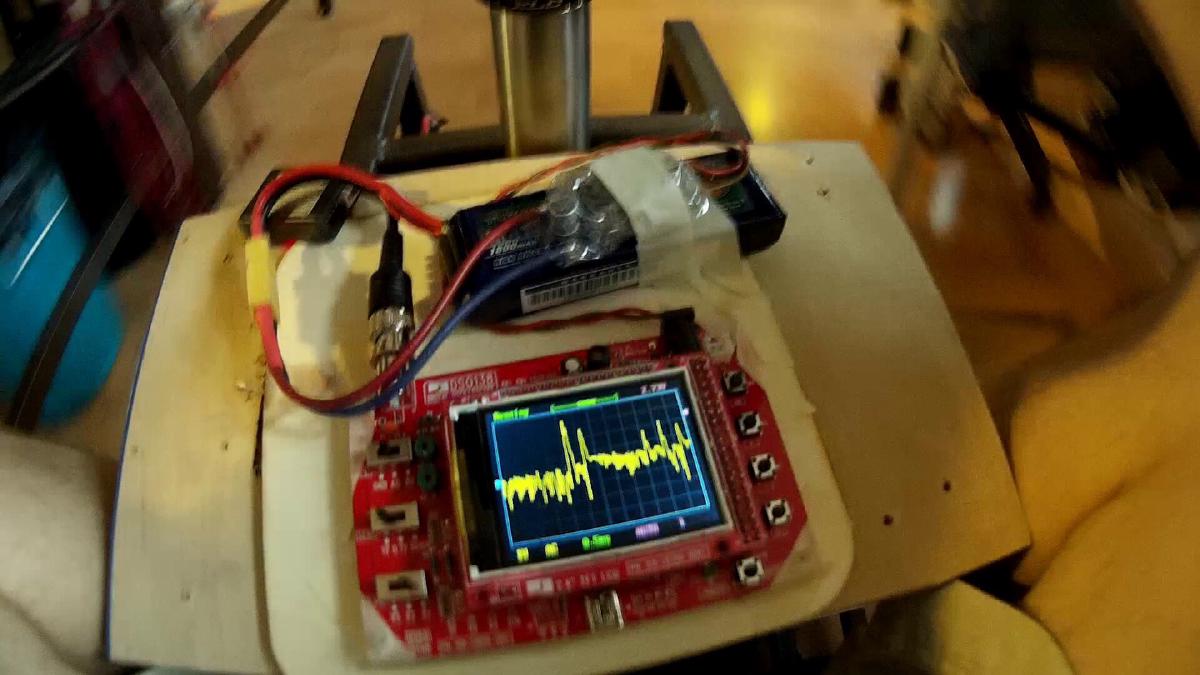
Mit einem “mini Oszilloskop” auf dem Kart hab ich die ripple Spannung am Eingang (50V) des Controllers gemessen. Hier zwei screenshots der Momente, als der Motor stottert. Zu den Zeitpunkten liegt der Akkustrom kurzzeitig bei etwas über 40A (könnte also die Stromlimitierung des Controllers sein (42A angegeben)) und der Motorstrom bei ca. 200A. Ob das nun Folgen des Stotterns oder selbst der Grund ist?
Um zumindest dem Einbrechen der Spannung entgegenzuwirken hab ich die beiden Einganskondensatoren (2x 470uF 100V) durch zwei 1000uF 63V ersetzt. Desweiteren die original Stromzuleitungen durch 10AWG Silikonkabel ersetzt und die dicken PCB Leitungen mit Lötzinn verstärkt.
Es kam mir vor als ob das Stottern dadurch seltener/später auftritt, es ist aber noch immer bei hoher Belastung da und so nicht akzeptabel.

Der Greentime controller ist im unteren Geschwindigkeitsbereich, trotz Sensoren sehr empfindlich und mit einem Gaspedal sehr schwer genau zu kontrollieren.
Mit einem Attiny13 hab ich eine Art Tiefpassfilter für das Gaspedal auf lochraster aufgebaut. Mit den zwei dip Schaltern lassen sich 4 Modis mit voreingestellten Werten einstellen.
Download Sourcecode & Hexfile: throttlefilter_20150906


Hier mal das Verhalten am Oszilloskop (500ms/div). Blau ist der Eingang, Gelb der Ausgang vom Filter. Dadurch wird nun das ruckartige Anfahren unterdrückt.

Obwohl der Controller mit dem Stottern nicht optimal ist sind wir endlich mal zu einer ausgiebigen Testfahrt gekommen. Erkenntnisse:
- Controller Scheiße (war ja schon klar)
- Cart fährt leicht nach links wenn Lenker und Rad gerade stehn. Hinterachse schief?
- Lipos fallen raus. Besser befestigen!
- Hinterräder im nicht-crazymode weniger stark neigen. Stopper vergrößern.


Am 4.10.2015 haben wir dann ein kurzes Video zum CrazyCart gedreht: