IoT Doppelrollo
Januar 2021
Inhaltsverzeichnis
- Heimautomatisierung
- Sensor ESP
- Multiroom Audio
- IoT Doppelrollo
- Personenwaage
In diesem Projekt geht es um das Automatisieren von Handelsüblichen Doppelrollos.
Doppelrollos zeichnen sich durch einen Vorhang aus, der oben am Fenster befestigt ist und ebenfalls oben aufgerollt wird. In der Falz liegt eine Stange als Gewicht, um den Biegeradius gering zu halten. Durch Ziehen an einer Kordel kann das Rollo aufgerollt werden. Manche Rollos verwenden ein Muster aus abwechselnd klaren und undurchlässigen Teilen. Damit ist es möglich durch wenige Zentimeter Bewegung zwei klare Bereiche voreinander zu bringen, wodurch mehr Licht hindurch scheinen kann.
Diesen Mechanismus durch einen Motor auszutauschen schien viel zu einfach. Und schwupp, ein neues Projekt.
Leider hab ich kein Foto vom Urspungszustand gemacht. Daher hier nur ein Bild von dem Bauteil, was ich ersetzt hab.
Der Motor ist ein Gleichstrom-Getriebemotor TDY-12 mit 15 U/min bei 12 Volt.


Wie in diesem Foto zu erahnen sollen zwei Fenster bestückt werden. Die gedruckte Halterung wird in die am Fenster montierte Klemme geschoben. Mit 15 U/min ist die Übersetzung des Getriebes hoch genug, dass die Reibung ein selbstständiges Abrollen verhindert. Ich habe mich dazu entschieden die Motoren an der Griffseite anzubringen, da sie hier nicht beim Öffnen an der Wand eingequetscht werden. Damit war es jedoch nötig Kabel über die gesamte Fensterbreite nach außen zum Scharnier zu führen. Ein paar gedrucke Kabelclips haben es wieder ordentlich gemacht.


Ein großes Problem besteht bei dieser Art von Rollo jedoch. Wird es zu weit auf oder abgerollt kann das Material abreißen. Damit wurde es sehr wichtig mindestens die Endpunkte sensorisch zu erfassen. 2010 habe ich dieses Problem bereits mit Reed Kontakten und Magneten am Rollo versucht zu lösen. Eine leichte Verschiebung der Kontakte oder Verlust der Magnete führt jedoch zum genannten kritischen Fehler.
Dieses Mal sind es Lichtschranken geworden. Diese bestehen aus einer Infrarot LED und einem der Wellenlänge entsprechendem Fototransistor. Knapp unter der Rolle angebracht kann Licht durch den Stoff scheinen und von der Lichtschranke erkannt werden. Ein schwarzer Streifen aus Isolierband signalisiert das obere Ende des Rollos.


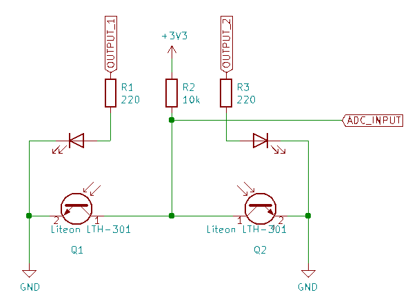
Ein ESP8266 (Wemos D1 mini) dient der Steuerung beider Rollos und verbindet diese mit dem IoT WLAN. Als Motortreiber dient das “Wemos D1 Motor Shield”, was auf TB6612 basiert und per I2C angesteuert wird. Mit dieser Doppel H-Brücke lassen sich direkt beide Motoren unabhängig voneinander antreiben. Durch Verwendung eines 10k Ohm Widerstandes als Pull-up an den Fototransistoren ist es zudem möglich analoge Werte aus der Gabellichtschranke (Liteon LTH-301) zu bekommen. Die Tatsache, dass der Stoff zwischen Klar und Weiß wechselt konnte ich mir somit zu Nutze machen. Der Aufmerksame Leser wird jedoch den Finger hebend “Aaaaber der ESP8266 besitzt nur einen ADC fähigen Eingang” sagen. Da ein Fototransistor jedoch hochohmig erscheint, wenn er nicht angestrahlt wird, können in diesem Fall beide Lichtschranken parallel verbunden werden. Durch zeitliches Multiplexing der LEDs über zwei digitale Ausgänge, von denen hat der ESP nämlich ein paar mehr, können beide Sensoren abwechselnd gemessen werden. Alle 25 ms lese ich somit den ADC aus und schalte jeweils kurz darauf die LEDs um.

Etwas länger habe ich mich mit der Interpretations dieser Messwerte erfasst. Die nachfolgenden Bilder zeigen deren Verlauf, wobei ich einen Medianfilter über die letzten 10 Werte als glättung anwende. Die mittlere Latenz von 2 * 25 ms * 10/2 = 250 ms ist dabei zu verkraften.
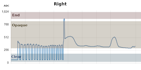
Wie unschwer zu erkennen ist unterscheiden sich die beiden Lichtschranken im Bereich des Weißen Stoffteils stark. Das kann zum Einen an Fertigungstoleranzen der Fototransistoren und LED’s, aber auch an der Sonneneinstrahlung liegen (siehe 3. Foto, bei dem das Rollo ab der Hälfte still steht).
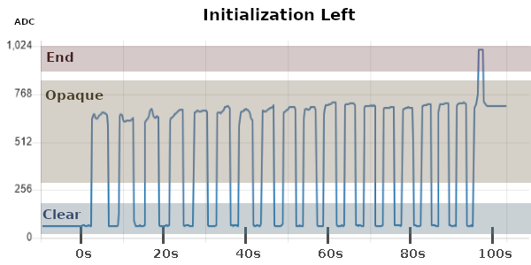
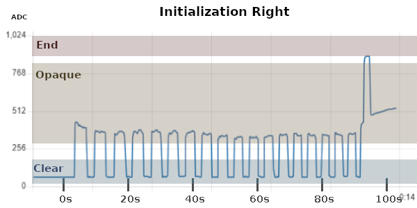
Die farblich markierten Bereiche zeigen die obere und untere Grenze, wie ich sie im Code in etwa definiert habe. Nach jedem Auslesen einer Lichtschranke wird versucht das Material in eine der drei Möglichkeiten (Clear, Opaque, End) zu klassifizieren.
Dadurch, dass die Bewegungsrichtung durch den Motor vorgegeben ist, sollte sich die Position der Rollos bestimmen lassen. Dazu muss jedoch zu Beginn eine Referenzposition angefahren werden. Hier kommt die schwarze Markierung am oberen Ende des Rollos ins Spiel.
Nehmen wir uns den Graph zu “Initialization Left” als Beispiel, bei dem der Motor das Rollo nach oben fährt. Zum Zeitpunkt t=0 s bis t=95 s ist nicht bekannt, wie weit der Stoff bereits aufgewickelt ist. Bei etwa t=95 s wurde die Markierung erkannt. Hier kann die Position als 0 mm (oben) angenommen werden. Danach ist es möglich die Position bei jedem Übergang von Klar zu Weiß und Weiß zu Klar zu aktualisieren, da die Längen dieser Bereiche mit 50 mm (Klar) und 74 mm (Weiß) bekannt sind.
Damit auch Zwischenpositionen angefahren werden können hilft ein digitales Abbild Prozessdynamiken zu simulieren, solange keine Änderung des Materials an der Lichtschranke festgestellt wird. Dieser “digitale Zwilling” beachtet dabei die Geschwindigkeit und Beschleunigungsrampe der Motoren für Auf- und Abwärtsfahrten. Die Geschwindigkeit hängt dabei zudem von der aktuellen Rolloposition ab, da der Stoff sich bei gleicher Drehzahl schneller abwickelt, wenn mehr Stoff noch aufgerollt ist.
Weiterhin ist mit diesem Modell eine Fehlerprüfung möglich, indem beispielsweise die Abweichung zur Realität kontrolliert wird. Wird diese zu hoch stoppt das Rollo und ein manuelles Zurücksetzen mit Anfahren der Endposition wird erforderlich.
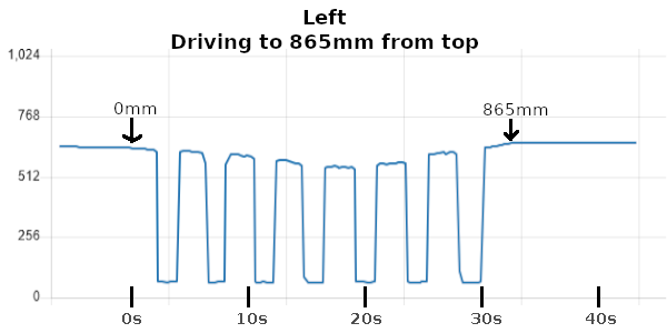
Das nachfolgende Bild zeigt dazu die Messwerte bei Anfahren der Position 865 mm (damit bewegt sich das Rollo 432 mm nach unten) von oben. Nach dem schwarzen Streifen (pos=0mm) folgen 27 mm bis zum ersten klaren Stoffteil. Sieben klare (7 * 50 mm = 350 mm) und sechs weiße (6 * 74 mm = 444 mm) Bereiche später fehlen nur noch 44 mm bis zur Sollposition. Diese Länge wird durch die Bewegungssimulation überbrückt, sodass das Rollo an in etwa der richtigen Position stoppt.
Wie immer fehlen noch die Gehäuse für die Motoren und Elektronik. Mehr Bilder folgen sobald es fertig ist.
CAD & Code: git.ctdo.de/interfisch/blinds_motorcontrol