Diversity Receiver
Januar 2014
Inhaltsverzeichnis
Einleitung
Antennendiversität (englisch “antenna diversity”) bezeichnet die Verwendung mehrerer Antennen pro Sender oder Empfänger bei der Funkübertragung, zum Beispiel als Strategie zur Reduzierung von Interferenz-Effekten. (Quelle: Wikipedia: Antennendiversität )
Im Modellbau ist es für FPV üblich, über mehrere Empfänger mit zum Teil verschiedenen Antennentypen das Videosignal zu empfangen. Ein Diversity Controller vergleicht dann und schaltet auf das bessere Signal um.
Die gängigsten Methoden zum Bewerten der Signalqualität sind der RSSI-Wert (Received Signal Strength Indicator), welcher als Analoger Spannungswert an vielen Empfängern abgegriffen werden kann und das Zählen der erkannten Sync Signale.
Um den RSSI aus einem RC305 zu bekommen, lötet man einfach einen Impedanzwandler an eine der Lötflächen des Reciever Moduls und fürt das Signal nach außen. Mehr dazu unter RC305 RSSI.
Die Horizontalen und Vertikalen Syncs bekommt man z.B. durch einen LM1881 Video Sync Separator. Die Beschaltung ist im Connection Diagram auf Seite 1 zu sehen. Erkennt der LM1881 eine neue Zeile wird an Pin 1 (Composite Sync Output) ein Signal ausgeben. Zählt man die Composite Syncs eine Sekunde lang bei einem guten Videosignal kommt man auf 16000 (bei PAL). Die Vertical Syncs kommen pro Sekunde auf 50 und geben sozusagen die (halb-)Bilder pro Sekunde an.
Wird das Videosignal schlechter werden durch Rauschen meist mehr Syncs gezählt. Durch die Abweichung vom Optimalwert (16000) lässt sich also grob auf die Signalqualität schließen.
Hat der Diversity Controller das bessere Signal ermittelt wird dieses über Relais oder besser mittels eines Analog Switch IC’s auf den Ausgang geschaltet.
Mein Vorhaben war es nun, einen solchen Diversity Controller selber zu entwerfen (Programmcode und Schaltung).
Sicherlich gibt es schon einige DIY Varianten, allerdings kam ich nicht immer an alle dort benötigten IC’s. Zudem lernt man ja mehr durchs Selbermachen.
Anfangen wollte ich mit dem einfachen Auslesen der RSSI-Werte und Zählen der Syncs von zwei RC305 5.8Ghz Empfängern.
Für meinen Div. Controller möchte ich möglichst beide Methoden implementieren. RSSI hat (so wie ich bei ersten Tests verstellen konnte) den Vorteil, dass es über den gesamten Bereich realtiv linear verläuft. Die Syncs hingegen sind bei guter bis mittlerer Videoqualität nah am Optimalwert, steigen aber bei sehr schlechtem Signal plötzlich stark an. Der Vorteil vom Zählen der Syncs liegt allerdings im tatsächlichen Auswerten des Videosignals (zumindest der Syncs). Wird das Funksignal z.B. reflektiert sind die Videodaten unbrauchbar, die Signalstärke (also der RSSI) ist aber weiterhin gut.
Die RSSI Werte müssen zu Beginn einmal Kalibriert werden, da nicht alle Empfänger die selben Spannungen bei 0% und 100% Signalstärke ausgeben.
Auch währe es hilfreich die ermittelten Werte direkt über die serielle Schnittstelle auszugeben und so mitzuloggen. Antennen ließen sich somit gut ohne teures Equipment vergleichen.
Als Mikrocontroller werde ich eine Atmega328 nutzen. Der Einfachheit halber verwende ich Arduino.
Der Code zum Auslesen von zwei RSSI und zwei Syncs war schnell geschrieben. Die RSSI lese ich an einem analogen Eingang ab. Es ist kein Spannungsteiler erforderlich da die RSSI Spannungen zwischen 0,4 und 1,2V schwanken. Die Sync Ausgänge der LM1881 sind an den zwei Interruptfähigen Pins 4 und 5 angeschlossen. Mittels Interrupt zähle ich einfach hoch und setze den Wert nach einer definierten Zeit zurück.
Die Ausgabe erfolgt seriell im CSV Format, die Werte werden also Pro Zeiteinheit (hier eine Sekunde) mit einem Semikolon getrennt ausgegeben. Unter Linux kann ich die Daten direkt in eine Datei umleiten und/oder ausgeben lassen.
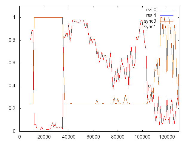
Das nachfolgende Diagramm zeigt den Vergleich zwischen rssi und Syncs (hier habe ich die Composite Syncs gezählt).
Zwischen 12000 und 35000 (Zeiteinheiten, x-Achse) ist der Sender ausgeschaltet, es werden aufgrund des Rauschens mehr als 65535 Syncs (Maximum für unsigned 16 Bit Integer) gezählt. Der RSSI Wert ist wie zu erwarten nahe des Minimums.
Zum Zeitpunkt 35000 ist der Sender eingeschaltet und befindet sich nah am Empfänger. Der RSSI Wert steigt stark an, die Syncs bleiben konstant auf 16000 (0,24 = 16000/65535).
Zwischen 50000 und 100000 bewege ich den Sender vom Empfänger weg und wieder hin. Der RSSI verhält sich dementsprechend. Die Anzahl der Syncs pro Sekunde bleibt größtenteils konstant.
Erst als ich den Sender mit meinem Körper abschirme, sinkt die Signalqualität so stark, dass die Syncs merkbar ansteigen. Das Bild ist zu dem Zeitpunkt aber schon stark verrauscht.
Am Empfänger war für diesen Test keine Antenne montiert, sonst hätte ich jedes mal recht weit laufen müssen. Die Grafik hab ich übrigens mit GnuPlot erstellt.
9.6.2014: Einige Zeit ist Vergangen nach den ersten Tests.
Bis jetzt besitzt das Diversity folgende Features:
- Lesen der Syncs/Sec und RSSI von bis zu 4 Receivern per Multiplexing (bis zu 8 mit wenig zusätzlicher Hardware möglich)
- Serielle Ausgabe im CSV Format
- Ansteuerung eines OSD (z.B. MinimOSD) zur Anzeige der Werte im Flug
- Receiverauswahl primär nach Videoqualität (Syncs), RSSI als Zweitkriterium
- Kalibrierung der RSSI Spannungen
- Verwendung von Relay-Stationen möglich (Deaktivierung des RSSI Einflusses)
Hinzukommen soll noch das Bewerten von Antennen. Wenn man z.B. zwei gleichartige Antennen gebaut hat und Testen möchte, welche besser Performt.
Wenn das Diversity Hardwareseitig bald komplett ist, werde ich es vom Breadboard auf eine geätzte Platine portieren.
Der Schaltplan, sowie der Code für das Diversity und das Minim ist am Ende der Seite zu finden.
Design und Schaltplan
15.3.2015: Viele Male hab ich das Diversity auf einem Breadboard mit mir zur Flugwiese geschleppt und auch benutzt. Bis auf das finetuning und unmengen an Wackelkontakten funktioniert alles wie geplant.
Hinzugekommene Features:
- Menü über das OSD zum Anpassen der Parameter, sowie speichern im EEPROM
- Soundausgabe durch kleinen Lautsprecher. Pieptöne in verschiedenen Tonhöhen beim Umschalten des Empfängers und als Feedback bei Kalibration ohne OSD.

Da ich in den letzen Monaten nicht viel am Schaltplan geändert habe wurde es mal Zeit für den ersten Aufbau auf einer geätzten Platine.
Da der interne Aufbau nicht ganz so einfach zu beschreiben ist, hier mal das Prinzip meines Diversity Controllers als Blockdiagramm:
Auf der linken Seite zu sehen die bis zu vier (mehr Theoretisch möglich) Eingänge [input x] , welche jeweils Video, Audio und die RSSI Spannung vom Empfänger übertragen.
Der Controller [Controller] steuert zwei Analog switches für Audio/Video [A/V Switch] , welche einen der Receiver zum OSD und somit auch zum Ausgang durchschalten.
Das MinimOSD [MinimOSD] bekommt vom Controller den anzuzeigenden Text übermittelt. Im Normalbetrieb also die RSSI Werte und den momentan ausgewählten Empfänger, im Menü dann den selektierten Eintrag und ggf. dessen Wert.
Welcher Videoempfänger den “besseren” Empfang hat wird u.a. vom RSSI Wert [RSSI] abhängig gemacht, die Spannungen gehen direkt von den Eingängen zum Controller. Nothing fancy!
Spannender dagegen ist das Ermitteln der Composite Sync Abweichung. Da der Atmega 328 nur zwei Interrupt fähige Pins besitzt, werden alle verfügbaren Videosignale kontinuierlich mit z.B. 4Hz durchgeswitcht [Video Switch]. Ein Sync counter [Sync Counter] (LM1881) zählt die Synchronisationsimpulse durchgehend und gibt sie als einfache Impulse an den Controller weiter. Da der Atmega mit zuvielen ausgelösten Interrupts, z.B. wenn das Bild nur rauschen enthällt, nicht klarkommt musste ich eine Art “Limiter” [Sync Limiter] vorschalten (bestehend aus einem einfachen Monoflop).
Zwei Buttons [Button x] zum minimalistischen Bedienen sind direkt am Controller angeschlossen und dienen zum Starten der Kalibrierung, Navigieren im Menü und zum manuellen umschalten der Receiver.
Für akustisches Feedback sorgt ein kleiner Lautsprecher [Speaker] mit Verstärkerschaltung [Speaker Amp].

Nun versuche ich mal die oben genannten Aspekte am Schaltplan zu verdeutlichen. Zuerst wollte ich alles auf eine Platine packen, einseitig da einfacher selber zu ätzen. Mit der kostenlosen Version von Eagle liegt aber das Größenlimit bei einer halben Europlatine, was doch deutlich eng wurde. Also bin ich dazu übergegangen, den Schaltplan in Analog und Digitalteil zu trennen und auf je eine 65mm x 100mm Platine zu Layouten.
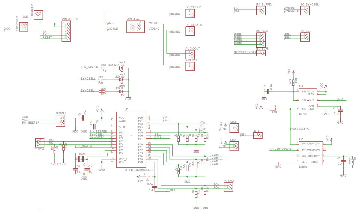
Folgender Screenshot zeigt den Digitalteil (vom 18.3.2015). Viel ist eigendlich nicht drauf: unten links der Atmega328P mit seiner Standartbeschaltung und entsprechenden Ein-und Ausgängen. PIN_BEEPER (PB0) ist der Soundausgang und geht zum Verstärker, welcher sich auf einem kleinen Addonboard befinden wird (siehe weiter unten). SYNCSEL0 und 1 ist die binäre Auswahl des Videosignals für den Sync Counter. Die beiden SYNCSEL Signale werden direkt zur analogen Platine geleitet, mittels BC_SYNCSEL. Alle Stiftleisten/Buchsenleisten mit dem Präfix BC (Board Connector) bedeuten eine Platinenverbindung von einem zum anderen Board. Die BC Verbindungen befinden sich auf beiden Platinen an den gleichen Stellen, sodass die obere mittels langen Stiftleisten auf die untere Platine mit Buchsenleisten gesteckt wird.
PB3, PB4, PC4, PC5, sowie INT1 haben in diesem Design noch keine Verwendung und gehen einfach an unbelegte Stiftleisten PB3PB5 und PC4PC5.
SEL0 und SEL1 sind, wie auch SYNCSEL die binären Auswahlen für den Ausgewählten Empfänger, im Blockdiagram also der lilane Pfeil vom Controller zum A/V Switch.
PC0 bis 3 sind analoge Eingänge, an welchen direkt die vier RSSI Spannungen anliegen.
BTN0 und BTN1 sind als je zweipolige Stiftleisten designed, an welche dann jeweils ein Schalter angeschlossen wird und den digitalen Eingang PD4 und PD5 beim betätigen auf VCC zieht.
Oben links ist die Buchsenleiste für den FTDI zu sehen, welche neben dem uploaden eines Arduino Sketches auch als serielle Schnittstelle zum MinimOSD dient. Das MinimOSD wird mit gerade Stiftleisten direkt auf die Digitalplatine gesteckt, Videoin und -out am Minim kommen in die 2x6-Polige Buchenleiste MINIM_AV .
Zuletzt noch unten rechts der LM1881 Sync Seperator IC, welcher das durch den Analogswitch gewählte Videosignal SELVIDFORSYNC in seine Synchronisationsimpulse zerlegt. Benötigt wird nur der Horizontale Sync (SYNCOUT Pin 1), welcher bei keinem Videosignal=Rauschen eine sehr hohe Frequenz hat. Um den Atmega nicht mit Interrupts zu belasten wird die Frequenz der Impulse durch einen als Monoflop beschalteten NE555 begrenzt (siehe z.B. elektronik-kompendium.de).
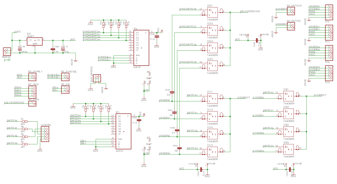
Kommen wir zum Analogteil :
Links oben in der Ecke befindet sich ein 7805 Spannungsregler. Aufgrund dieses 5V Linearreglers sollte die Eingansspannung des Diversity bei mindestens 7V liegen. Die Eingansspannung AVCC wird direkt an den Anschlüssen für die einzelnen Receiver anliegen. Da jeder der Boscam RC305 (die ich verwende) jeweils einen weiteren 5V Linearregler verbaut hat sollte die am Diversity angelegte Spannung nicht allzu hoch sein, um die Verluste gering zu halten. Am Effizientestens denke ich sind so 7,5V, die ich von einem effizienteren Schaltrelger “Stepdown Wandler” abgreife. Ein 2S Akku ist zu wenig.
GND_BRIDGE dient als verbindungspunkt von analoger- und digitaler Masse und wird nachher einfach gebrückt.
Wie zuvor erwähnt werden die Analogswitches für Syncauswahl und Empfängerauswahl vom Mikrocontroller binär selektiert um Pins zu sparen. Um die 74HC4066 Analogswitches anzusteuern werden aber wieder vier einzelne Signale gebraucht. Das schaffe ich mittelst jeweils einem 74HC4051 Multiplexer IC .
Ganz rechts im Schaltplan zu sehen: alle vier Anschlüsse für die Empfänger mit je Analoger Masse AGND , Versorgungsspannung AVCC , RSSI, Audio und Video. Die Boscam RC305 müssen für dieses Diversity den RSSI mit ausgeben, siehe RC305 RSSI.
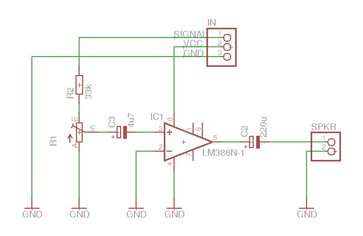
Für die Supermarktähnlichen Pieptöne sorgt eine kleine Addonplatine mit einem LM386 Audioverstärker. R1 ist ein Poti zum Einstellen der Lautstärke. Der Rest ist eigendlich selbsterklärend.
Alle Schaltpläne, Eaglefiles und PCBs gibts am Ende der Seite als zip.
Und nun ein paar Bilder vom Aufbau.


Hier nochmal die Platinen im Closeup. Links: Analogplatine, Mitte: Digitalplatine, Rechts: Soundboard


Die Buchsen- sowie Stiftleisten sind im Schaltplan alle als Pinheader eingezeichnet. Auf folgenden Bildern kann man sehen, welche davon Stift und welche Buchsenleisten sind. Die Stiftleisten von der oberen Platine sind zur Kupferseite der Platine angebracht.


Zuerst kommt das MinimOSD auf die dafür vorgesehenen Buchsenleisten auf der Digitalplatine, danach wird die kleine Soundplatine mit ihren drei Pins eingesteckt (auf den beiden andern Bilder noch nicht abgebildet). Obendrauf kommt dann die Analogplatine. Das ganze Passt perfekt in ein Kunststoffgehäuse. (LxBxH): 135x75x49 mm


Stromkabel sowie Video- und Audioausgang hab ich direkt auf die Platine gelötet. Die Empfänger werden je über einen 6-Poligen MiniDIN Stecker angeschlossen. Jede MiniDIN Buchse ist mit einem kurzen Kabel mittels Buchsenleiste auf die obere Platine gesteckt und wird durch herausgefeilte Schlitze zwischen Gehäuse und Deckel herausgeführt.
Den beiden Tastern hab ich noch je einen 100n Kondensator als Entprellung spendiert und einfach mit ans Kabel gelötet. An die 5-Polige Stiftleiste am Rand der Analogplatine werden vier LED’s angeschlossen, welche den momentan geschalteten Eingang anzeigen. Die LED’s dafür hab ich im Plastikgehäuse versenkt. Für die drei Status/Debug SMD LED’s auf der Unterseite der Digitalplatine sind drei kleine Löcher ins Gehäus gebohrt und mit Heißklebe abgedichtet.
Für die nervigen Piepstöne hab ich mir einen alten Lautsprecher aus einem Monitor genommen und mit ins Gehäus gequetscht.


Und fertig ist das Diversity. (In dem Bild fehlt noch neben der Videoout Cinchbuchse der Audioausgang)

Manual
Durch seine nur zwei Buttons ist das Diversity nicht ganz so intuitiv zu Bedienen.
Wer aber mit den 4-Button Chinaladern klarkommt sollte hiermit auch umgehen können.
Hier mal die möglichen Funktionen der Buttons:
| Button | Betätigung | Funktion | Funktion Menü |
|---|---|---|---|
| Button Rot 0/A | kurz | Diversity aktivieren | Zurück, Wert verringern |
| Button (Grü) 1/B | kurz | Manuell schalten | Weiter, Wert erhöhen |
| Button Rot 0/A | lang | / | Menü Zurück |
| Button (Grü) 1/B | lang | Menü öffnen | Eintrag wählen |
Um dem Diversity beizubringen welche Empfäger angeschlossen sind und wie der RSSI Spannungsbereich jedes einzelnen aussieht muss eine Kalibrierung vorgenommen werden:
- Dazu verbindet man alle Empfänger die verwendet werden sollen und stellt die Kanlöle korrekt ein. Das Aufschrauben der Antennen ist nicht zwingend notwenig. Wird ein Empfänger an einem anderen Eingang angeschlossen, muss das Diversity erneut Kalibriert werden. Der Videoausgang des Diversitys sollte hier breits an einem Monitor/ einer Brille angeschlossen werden.
- Danach schaltet man den Videosender mit angeschlossener Kamera ein , sodass dieser ein Bild sendet. Nicht vergessen eine Antenne an den Sender zu schrauben, sonst kaputt!
- Jetzt muss der Button 0/A gedrückt gehalten werden und gleichzeitig das Diversity Eingeschaltet werden, durch Einstecken des Stromkabels.
- Bei angeschlossenem Lautsprecher sollte ein hoher langer Piepton erklingen. Der Button muss dann sofort losgelassen werden. Im OSD sollten oben nun die aktualisierten RSSI Werte angezeigt werden.
- Der Videosender muss nun zum Ermitteln der maximalen Werte langsam zu jedem Empfänger hin bewegt werden. Für die minimalen Spannungswerte reicht es, den Sender auszuschalten und ein paar Sekunden zu warten. Danach wieder einschalten.
- Um die Kalibrierung abzuschliessen und die Daten im EEPROM zu speichern muss der selbige Button kurz betätigt werden. Der Lautsprecher bestätigt den Tastendruck und das OSD weist ebenfalls darauf hin.
Hauptbildschirm
Nach Abschluss der Kalibration bzw. nach Einschalten des Diversitys ist der Hauptbildschirm zu sehen, sofern mindestens einer der Empfänger ein Bild empfängt. Das OSD des Diversity kann temporär verschwinden, wenn das Videosignal verrauscht ist.
Nur die obersten zwei Zeilen werden vom OSD verwendet um nicht mit einem OSD des Flugmodells zu kollidieren.
In der obersten Zeile werden die normalisierten RSSI werte [0,255] mit Querstrichen getrennt angezeigt. Von links nach rechts: Receiver 0 bis 4. Waren bei der Kalibrierung nicht alle Eingänge belegt (bzw. manche RSSI Spannungen zu niedrig) sind die entsprechenden Eingänge deaktiviert und werden auch in der Anzeige übersprungen.
Vor einem RSSI Wert kann eines der Symbole #, ~ oder M stehen. M bedeutet, dass der Eingang manuell gewählt wurde; der Diversity mode ist hierbei deaktiviert. Das Zeichen # zeigt an, das der Empfänger anhand der Sync-Impuls Abweichungen gewählt wurde. War die Syncabweichung nicht der entscheidende Grund, sondern der RSSI Wert, so ist das Zeichen ~ zu sehen.
Menü
Die Navigation im Menü erkläre ich demnächst anhand einer supergeilen Grafik!…
Files:
Hardware:
-
Latest: Version 20150318b
- Fix wrong capacitor value (C11) for digital schematic
-
- diversity_analog: Pinheader boardconnection polarity fixed, pcb unchanged. Use firmware >= 20150318
-
- Pinheader boardconnection moved
Firmware:
-
Latest:Version 20150719
- added different beep for sync selection
- calibration min/max update beeps
- syncrating now means the counted and normalized syncs [0,16000], 16k=best
- changed syncrating to syncfails, bestsignal: syncfails=0. worst syncfails=16000
- calibration sets sync-only/deactivate receiver automaticly
- added looptime counter to debug menu
- finer adjustment for rssi smoothing alpha value over 85%
- fixed rssi average filter calculation
- new diversity osd screen, change screens in diversity mode by pressing button A
- lastselectedby sustains until receiver switched
- automatic switch sound muting if signal is bad for some time
- minimdiversityosd.ino: added sync change commands
-
- changed rssi comparison to compare to bestrssi instead of bestsyncrating (compareAndSelect)
- inverted rssi smoothing: higher value=smoother
- added MINSYNCCONNECTED: if rawsync is below receiver will not be selected by sync (for temp disconnected receivers)
- removed RSSI_DISCONNECTED, temp disconnected receivers will be noticed by low sync (see MINSYNCCONNECTED)
-
- added RSSI_DISCONNECTED to avoid switching to a not connected receiver input
- added receivermode 0-3 to eeprom
- added receivermode 0-3 entries in debug menu, hold B to cycle trough the modes
- added MAXSYNCFAILS, so that static is better rated than blackscreen(not connected)
-
- Atmega pin changes for better pcb layout.Use PCB version newer than 20150313
- Debug menu entry