Project start: April 2015
Miniquad
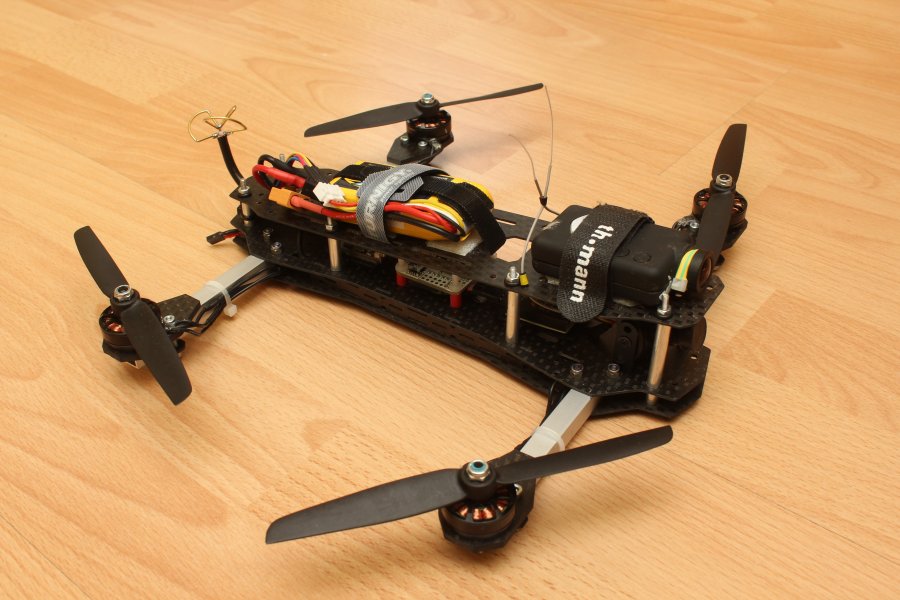
After a while, i needed something else than slowly hovering around with my tricopter. So a FPV Miniquad seemed like a great alternative.
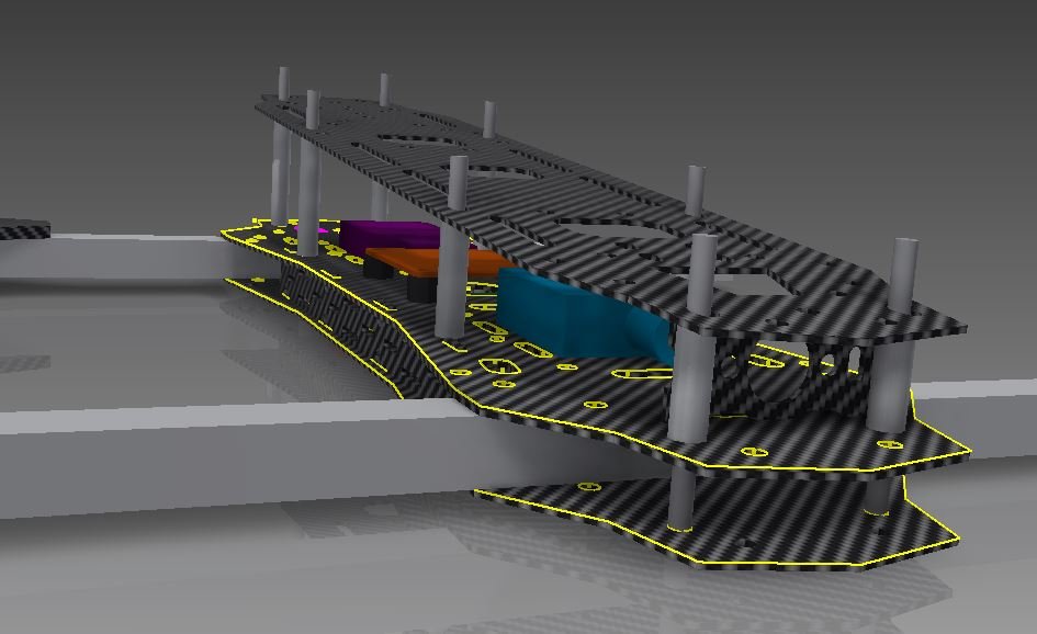
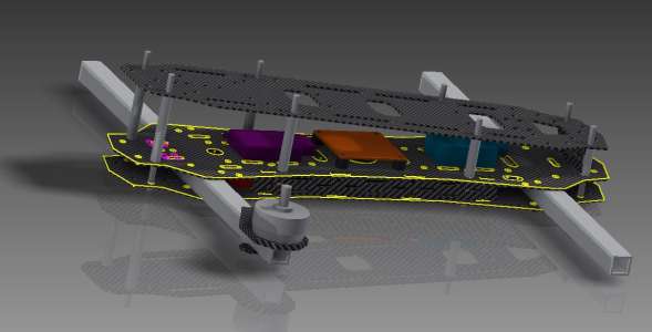
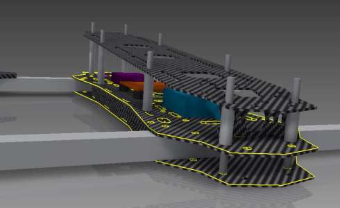
Because of the price and my pride, buying a frame was not an option. So i started to design my own frame in Inventor at the beginning of this year (2015).
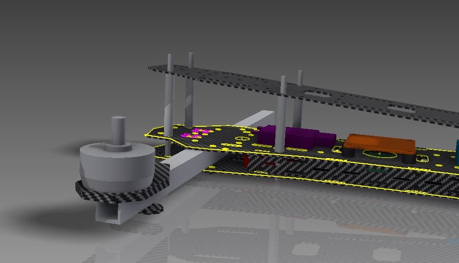
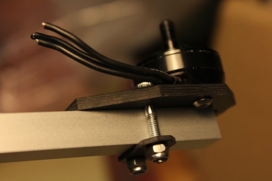
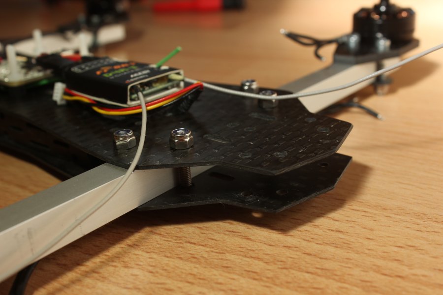
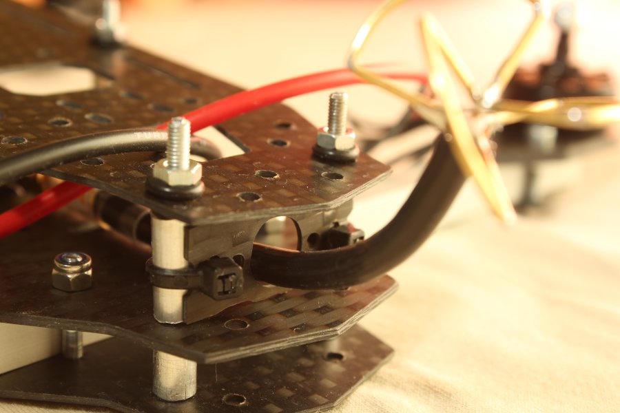
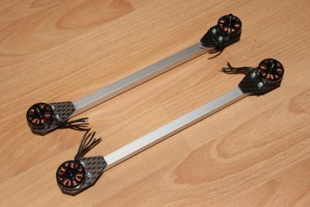
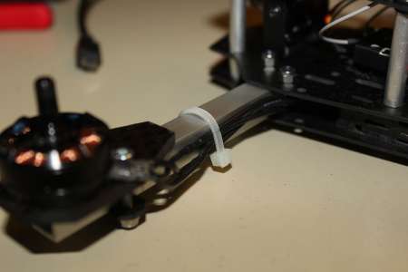
Unlike most of the miniquads i wanted the arms going straight through the centerplates rather than screwing flat carbon arms at each side. I decided to use 10mm x 10mm square aluminium tubes, wich are a bit softer than carbontubes but in case of a crash they'll just bent and maybe not break.
To not add breaking point so the aluminium they'll get squished between the centerplates, same with the motormounts. Also its easier to change the arms if they got bent.
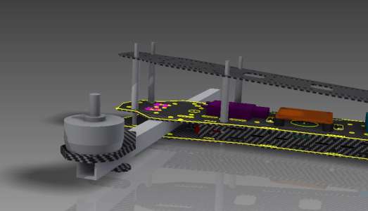
Furthermore, the upper CFK plate is slightly angled to the centerplate. Normally the camera on top gets tilted upwards (resp. the motors tilted forwards) so you get to see more than the ground. Since there is not much tall in the back of the quad, it was possible to tilt the whole topplate and saving some space. With this construction the mobius can now be mounted flat and is still tilted upwards about 5°.
Here some technical details:
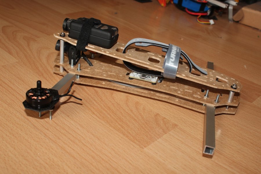
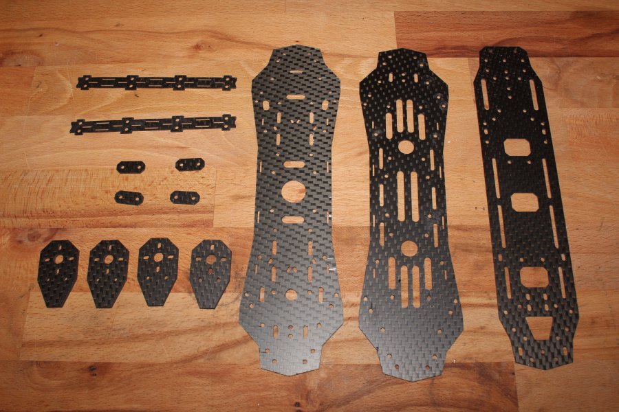
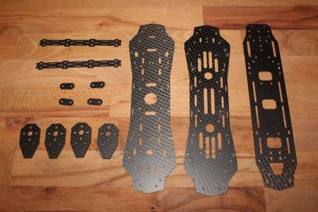
To see if everything fits as planned i first milled the frame out of cheap hardboard.
I ordered the cfk sheets from
Hadeg-Recycling.
For the lower centerplate i used 1mm thick cfk, the one above is a litte thicker (1.4mm). Like the lower centerplate, the topplate is 1mm cfk. The two small strips are 1.4mm thick and go on the left and right side between both centerplates.
In a crash, the motormounts have to withstand the most force. So i used 3.2mm cfk. For the small plate at the bottom 1.4mm should be enough.

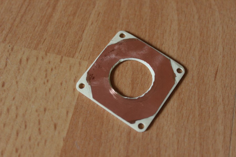
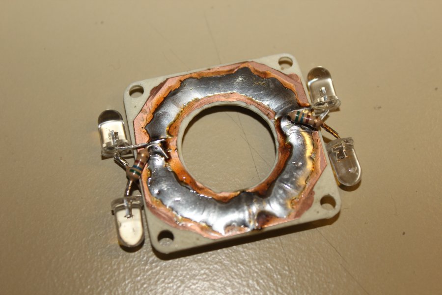
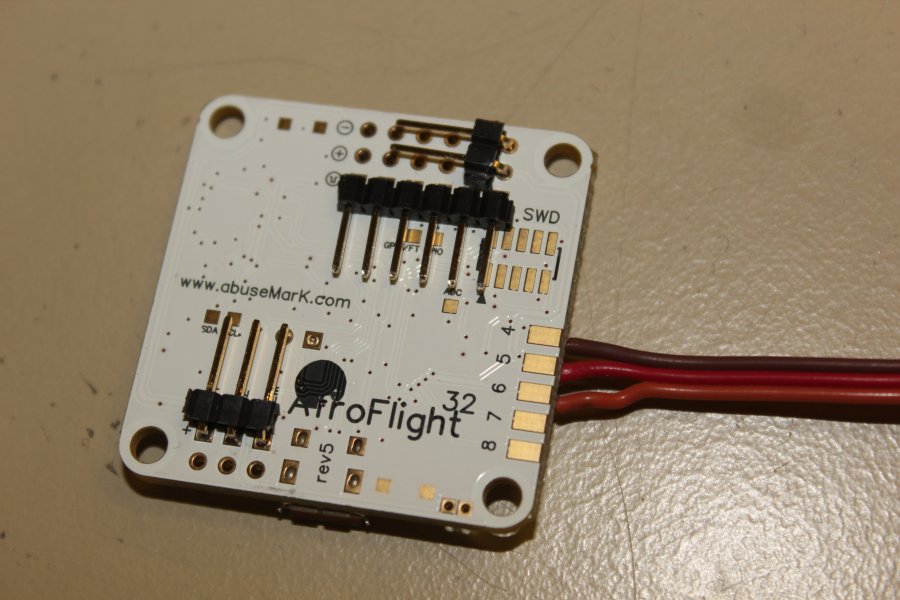
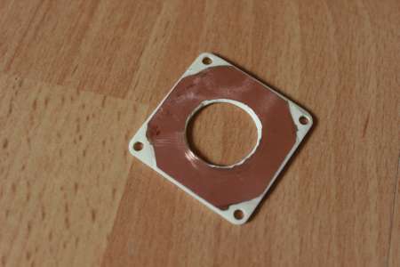
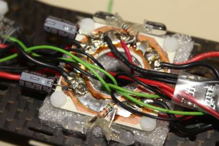
The Powerdistribution consists out of a double sided copper board the size of the Naze32 (distance between holes: 30,5mm).
On the sides there was enough space to fit two red LED's each.
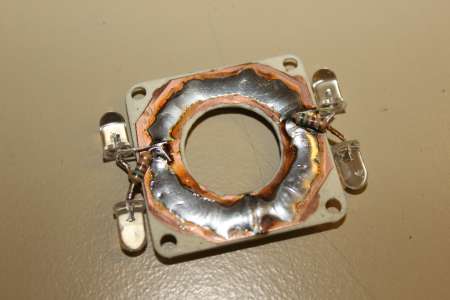
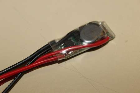
The BEC from XXL-Modellbau had a capacitor on the inputside wich i had to remove to fit the BEC together with the PDB between the centerplates (10mm height).
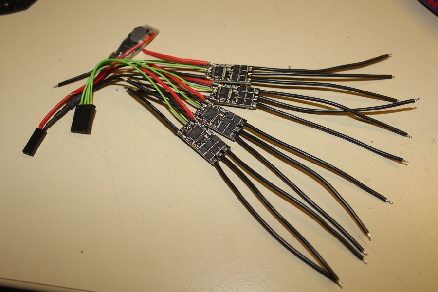
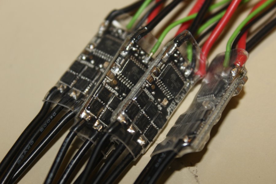
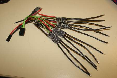
Additionally I soldered the groundconnections of the ESC's to the BEC Ground. All four ESC signalwires are wired to one four pin connector. Before heatshrinking the ESC's I soldered the jumper JP1 to enable Oneshot125. By doing that, the controllers only accept oneshot signals. In the Baseflight configuration you have to enable the features "SYNCPWM" (for Oneshot) and "FASTPWM" (for the 125us timing).

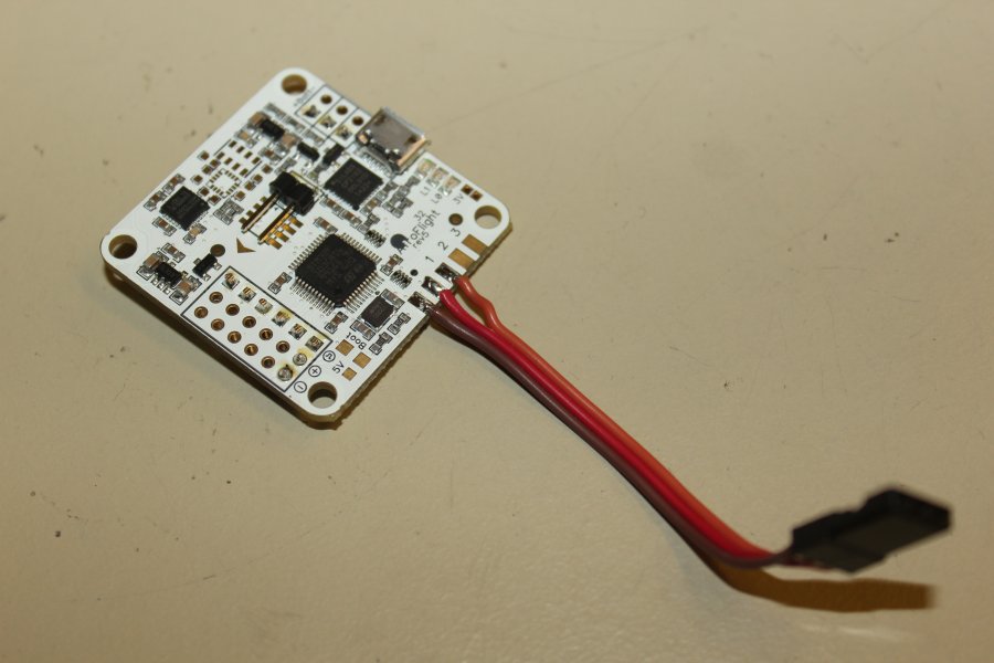
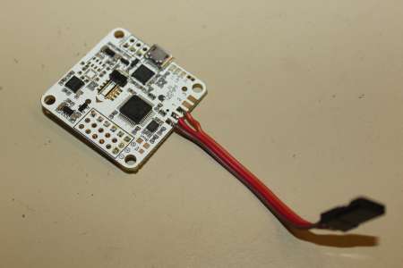
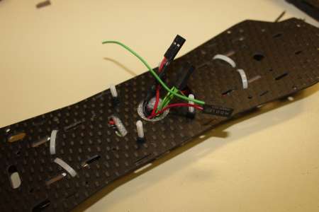
On the Naze board i tried to build as flat as possible and only soldered connectors where they were needed. To keep it flat, most pinheaders are angled and soldered at the bottom side.
The D4R receiver is able to output a CPPM signal on channel 1 if the signal pins of channels 3 and 4 are bridged. With that, a short piece of servocable is all you need to connect the receiver to the flightcontroller.
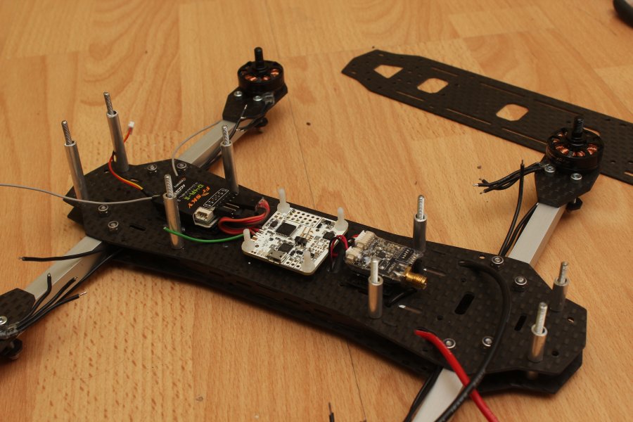
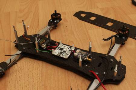
Back to the powerdistribution; The PDB is hold in place by four plastic screws wich also hold the Naze32 on the otherside of the Centerplate. Between the board and the conductive cfk a scrap piece of foam is used as a spacer and as isolation. For good conscience i placed two 100uF caps to the main power leads.
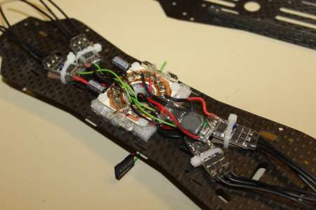
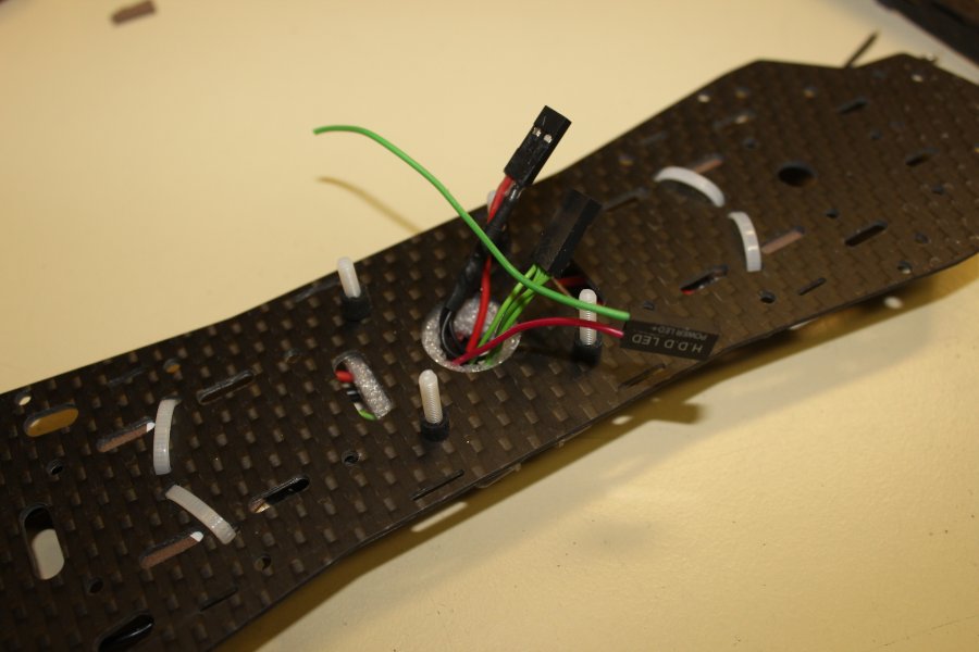
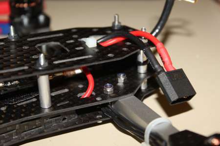
5V, the wire for voltage measurement and the ESC signalwires find their way up through the big holes in the middle. There they are connected from underneath with the flightcontrol. The Frsky receiver and the 5.8Ghz videotransmitter are placed in front of and behind the FC and held in place by some velcro.
Both 16AWG power leads fit nicely through two slots right before the rear arm.
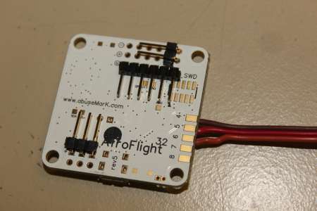
To make it easier to connect the Naze to a computer, I turned the board 90 degrees clockwise. In the configurator you have to type "set align_board_yaw=90" into the CLI.
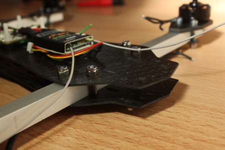
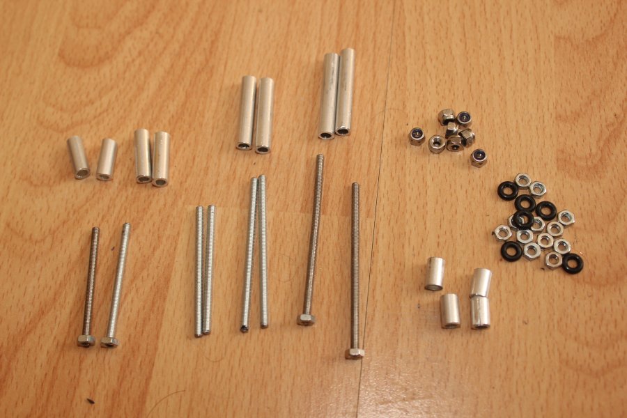
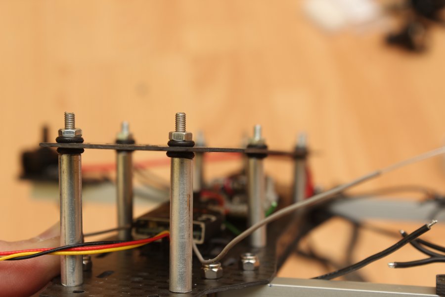
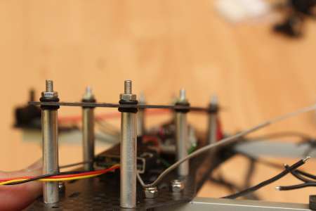
As spacer for the topplate i used some aluminiumtubes (6mm outer diameter) with following lengths: 15mm, 22mm, 28mm und 35mm. These are slightly angled at one end.
Accordingly the lengths of the M3 skrews are: 40mm, 45mm, 54mm und 60mm.
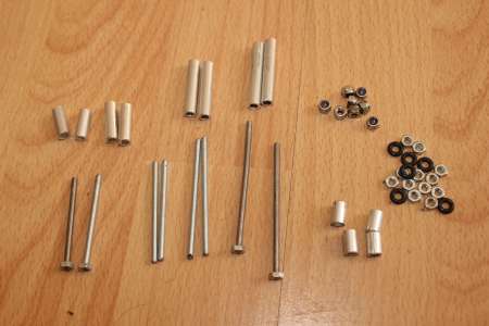
On each side of the topplate two rubber rings should dampen some vibrations.
For the 5.8Ghz antenna i used a aircell5 cable and a RG58 crimp connector. The antenna gets screws onto the transmitter at the inside and is feed through a small plate at the back of the copter to prevent it to bent into the props. The hole is 10mm in diameter, just big enough to put the RP-SMA connector through.

The siliconwires are tied to the topplate with cableties as a cable relief.
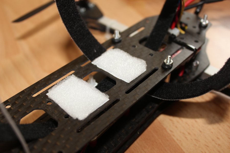
The Lipo gets tightened on the top with some velco straps. The thin foam pieces are there to prevent the battery from sliding around. The mobius camera at the front has also some foam underneath for the same reason and as a vibration dampener. Maybe i will change them later by something better.

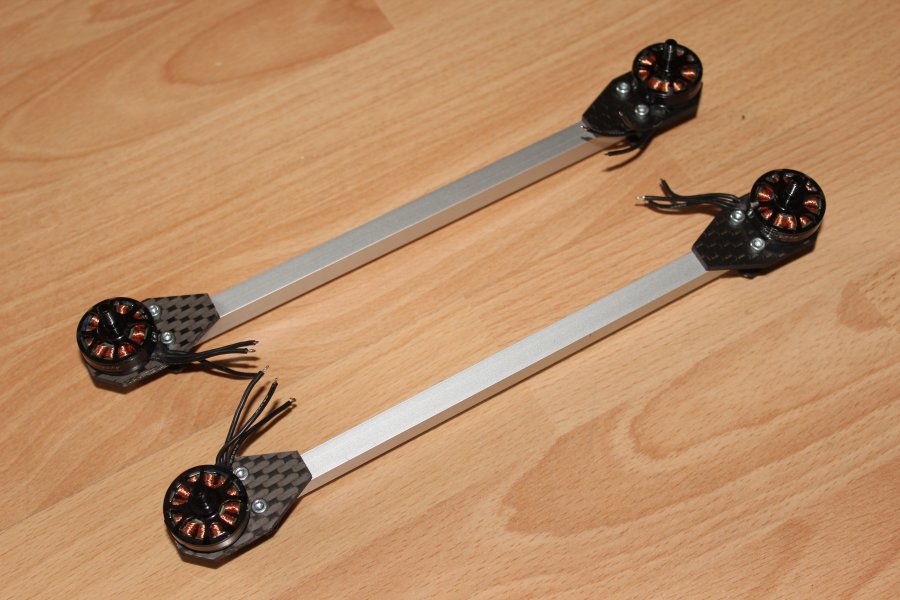
Soldering the motorwires, checking the rotation and securing the wires with a cabletie was easily done.
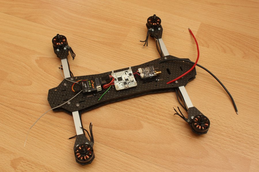
Because I'm such an incredible rebel, I chose the motors to turn all the opposite direction as suggested in the Naze description, so that the front right propeller spins clockwise. If you reverse the yaw_direction by typing "set yaw_direction=-1" into the CLI it works just fine. Don't know if its a real advantage but i see no disadvantages.
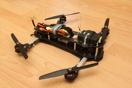
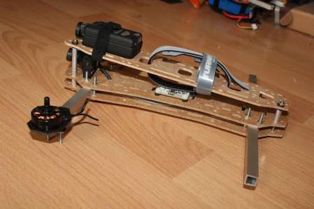
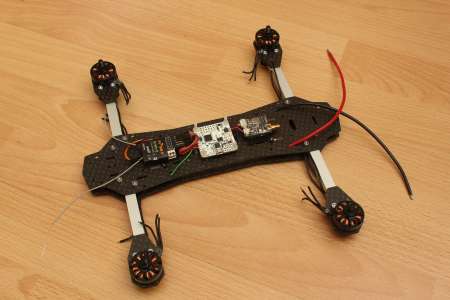
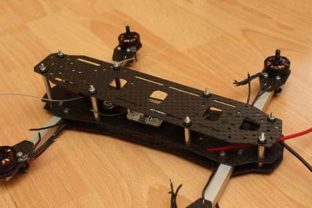
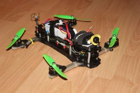
And there she's finished:
I didnt even changed the PID's, it flew just fine with the default ones.
With the 6030 HQ Props (carbon reinforced) on 3S and an AUW of approx. 560g i measured 7.7A hover current and 32A peak.
And here some footage of the first flights.
And here some faster weekend flights:
18.4.2015
19.4.2015
July 2015, a lot of flights were made since I build this quad. The aluminium arms needed to be bend back or exchanged after some very bad crashs, the rest of the frame seems quite reliable.
For cost reasons I went to the Gemfan 5040 props, wich are only half the price of the HQ Props.
I did some simple current tests with various props. The miniquad was equipped with a 3S 2200mAh Lipo.
| Prop | Hover | Peak |
|---|
| HQ 6030 | 7.7A | 32A |
| Gemfan 5040 | 6.8A | 31.1A |
| DAL6040 Bullnose 5" | 10A | 51A |
| DAL6040 Bullnose 4.5" | 7.2A | 43.8A |
Now it is 2016 and it had to disamble the quad for the first time because all nylon screws wich hold the FC were broken.
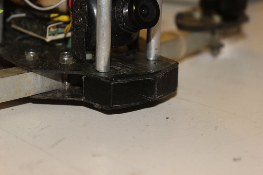
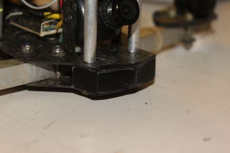
The carbon in the front started to come apart slowly. Also I got annoyed by all the dirt which gets stuck between the carbon frame on almost every muddy crash, so I put a 3D printed part in there.
Files
DXF Files:
Version 20150326
Settings and PID Dump
 PID's
PID's