PTZ Movinghead
December 2024

The device consists of a base to which a circuit board with an RJ45 socket for power supply, control signals, and video is attached. All signals are transmitted to the rotating part via a slip ring with 12 contacts. Two stepper motors are mounted on it. The stepper motor drivers are located on another circuit board together with other signal processing components. The arm for the tilt axis is mounted perpendicular to the first axis of rotation. This carries the camera module with focus, zoom, and motors for the aperture. The camera only needs to be able to rotate 90°. A micro switch is used to reference the tilt axis. Since the pan axis can rotate infinitely, a Hall sensor was installed instead of a hard end stop.

I rejected the idea of continuing to use existing motor drivers and figuring out the control system because the circuit boards also contained the camera control system, which I no longer need. This would have made me less flexible when adding new functions.

I still had a few TMC2130 drivers left in my assortment boxes, as well as an ESP8266. A little while later the first axis was moving.

It was not easy to try out the movements with wires getting draged around. So there was an incentive to quickly draw up a circuit board for the ESP and stepper motor drivers.
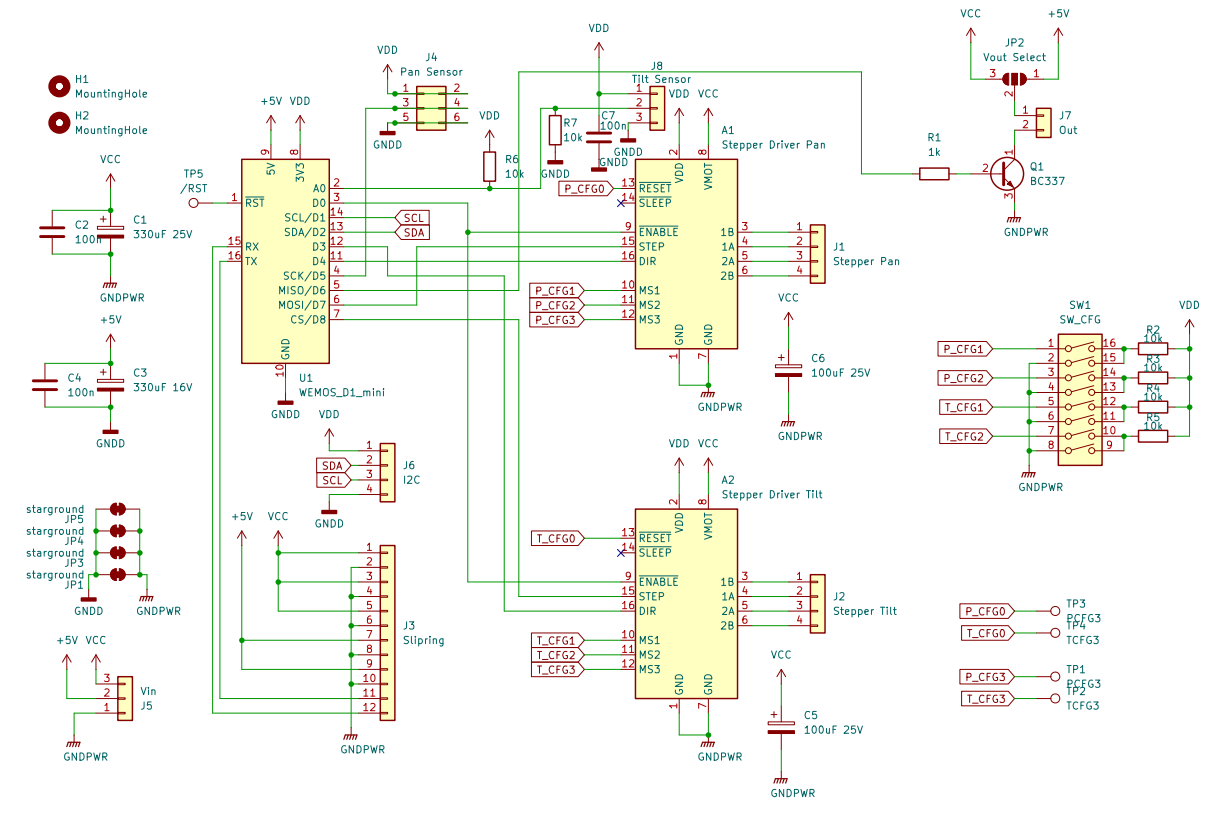
I desoldered a few components from the original circuit board and reused them. In addition to the sockets/plugs for motors and slip rings, these were the DIP switch (for configuring the TMC drivers) and the Hall sensor on a small circuit board, which will later pass just above the magnet mounted on the base.


The ESP can be connected to the Wi-Fi. This means that only the power supply is required as a physical connection. If continuous rotation is not required, it is sufficient to route the three cables through the center and leave the slip ring removed. Three cables because I generate 5V logic voltage and the approx. 19V motor voltage externally.
However, I have routed the UART of the ESP through the slip ring. I don’t want to rely solely on wireless.

As mentioned, the reference movement of the pan axis works via a Hall sensor and magnet. Since I don’t need the camera cage, the tilt axis can now also rotate endlessly. In addition to the larger pinion, another Hall sensor (latching) is attached. A mounting bracket for the actuator is screwed directly onto the pinion. It contains a small magnet on the outer edge, which defines the zero point of the tilt reference movement.


The power supply board is attached to the side of the base. Here, I use the same screws that were used to attach the original board. On it the connector for the slip ring can be found and a step-down converter, which I copied 1:1 from the off-the-shelf module at the bottom left of the picture. UART is connected to the pin header.

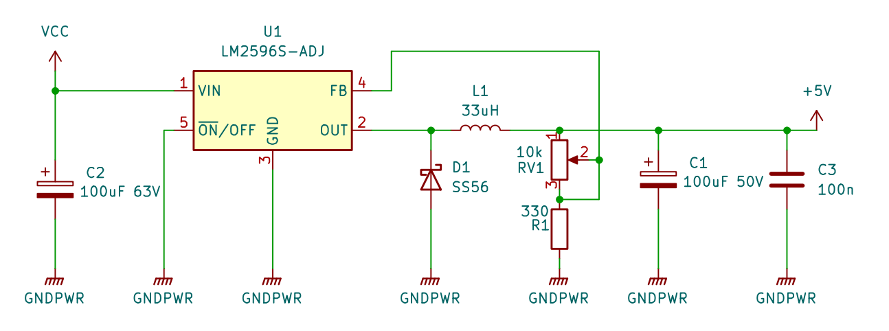
20260110_schematic_powerboard.pdf
With a little code, the moving head already works.
To test the movements, I first implemented the reference movement.
Then it waits for Artnet packets in the format: pan_coarse, pan_fine, tilt_coarse, tilt_fine, dimmer.
I think I divided the movement range into 720° for 16 bits, but that’s easy to change later.
It’s nice to see the motors turning, but moving a beam of light through the room would be even more exciting.
I would have liked to use an LED flashlight with a narrow beam. Unfortunately, I couldn’t find anything suitable. However, using the search term “fat beam laser” will bring up laser modules that produce a spot measuring just a few centimeters. In the picture, these are the two aluminum tubes with 532 nm (green) and 405 nm (violet).

Inside is the laser diode, whose light is collimated by a lens in the front section of the aluminum tube. Since inexpensive lasers often emit infrared light in addition to the desired wavelength, I have already installed an infrared blocking filter in the one on the right, which I came across when dismantling the camera. More on that later.

Laser diodes are driven with constant current. The driver can be found in line with the wires. The potentiometer is used to set the current.


I replaced the PVC-coated strands with silicone wires so that they last a little longer and are easier to lay. In addition, I added a printed cap to the cable outlet, as this protrudes from the side of the moving head and is most likely to be damaged during transport.


The moving head will serve as a basis for various ideas and can therefore be easily converted from a laser pointer to something else. All attachments for the laser can be easily removed with just a few screws.
The tube is clamped to the pan motor with a C-clamp. The tilt movement is created by a mirror at a 45° angle to the axis of rotation. A piece of a HDD platter (not the glass kind) that has been cut out serves as the mirror.


The lasers are supplied by 5V. A transistor enables the ESP to control the light.


Files:
git.ctdo.de/interfisch/ptz_movinghead