Laser Power Meter
January 2026
A cheat way of measuring this is a thermopile. Here a peltier element is cooled enough on one side, so that the temperature does not increase significantly. Through input energy from the other side a temperature difference is created and through the Seebeck effect a voltage differential is created. This voltage depends on a number of hard to calculate factors but it is proportional to the power and thus could be calibrated with resistive heat elements.
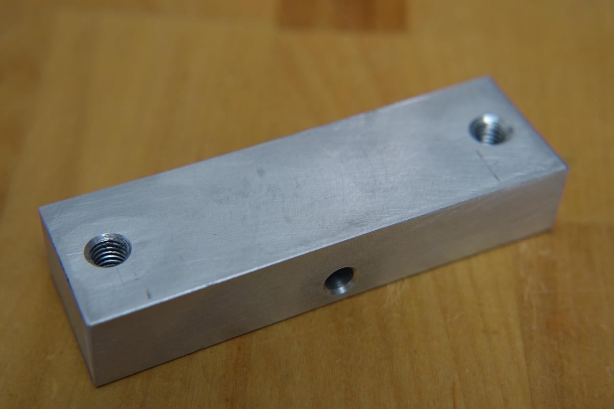
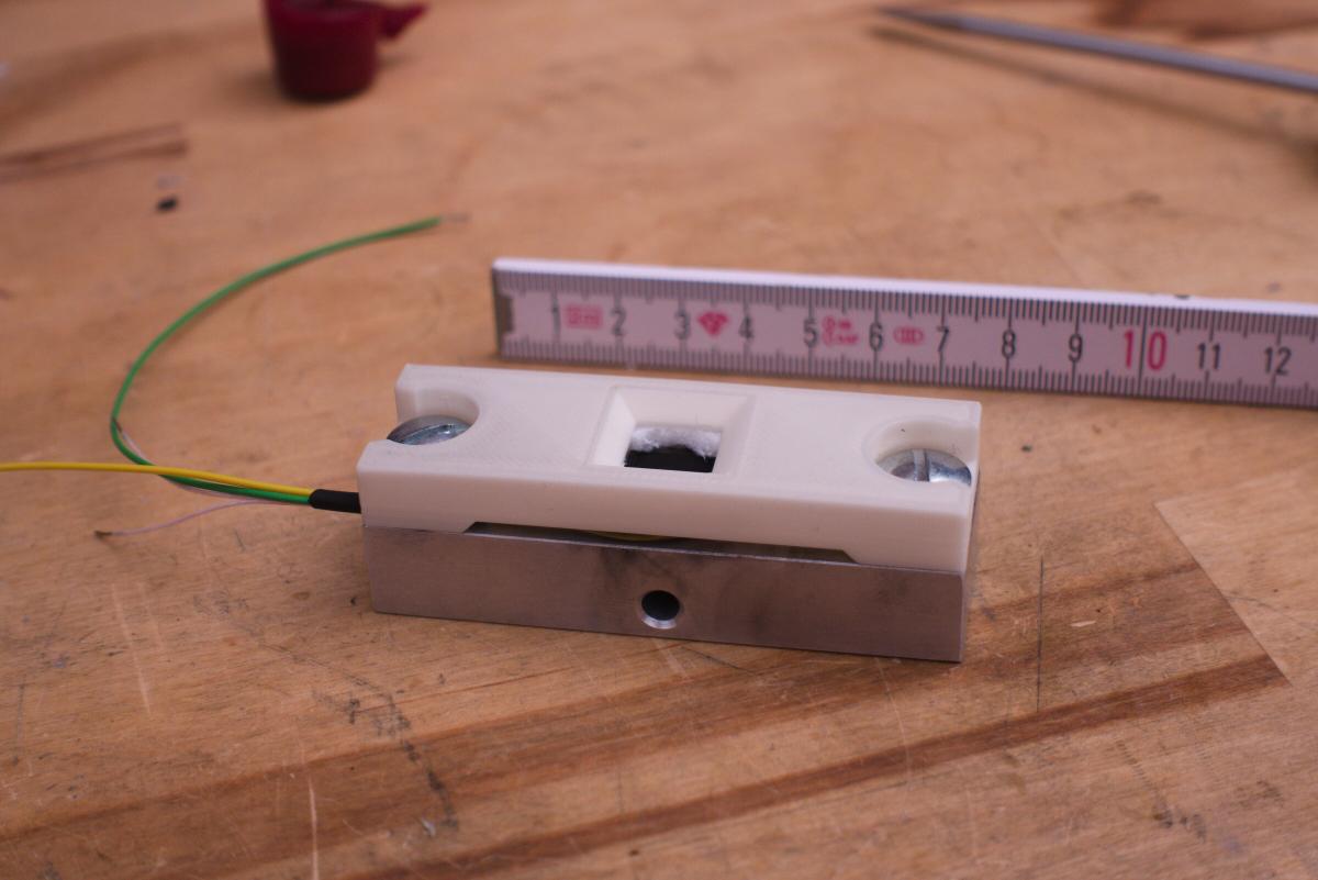
But one after the other. We’ll start with the heatsink. I want to measure the power up to 200 mW. A scap piece of aluminium with threaded holes in just the right places was perfect. With a size of 80mm x 25mm x 15mm is has a volume of 306 cm3 and likely enough thermal mass to sink 200 mW over a couple of minutes.
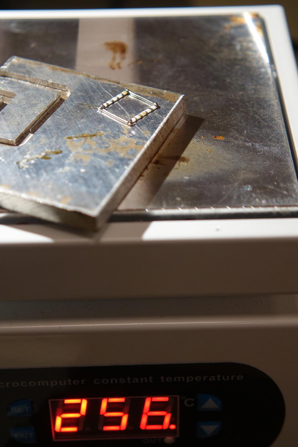
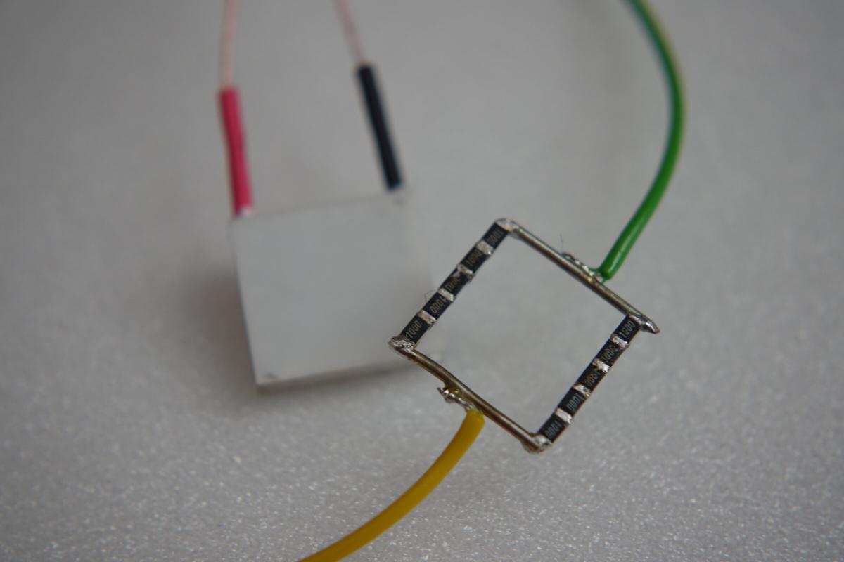
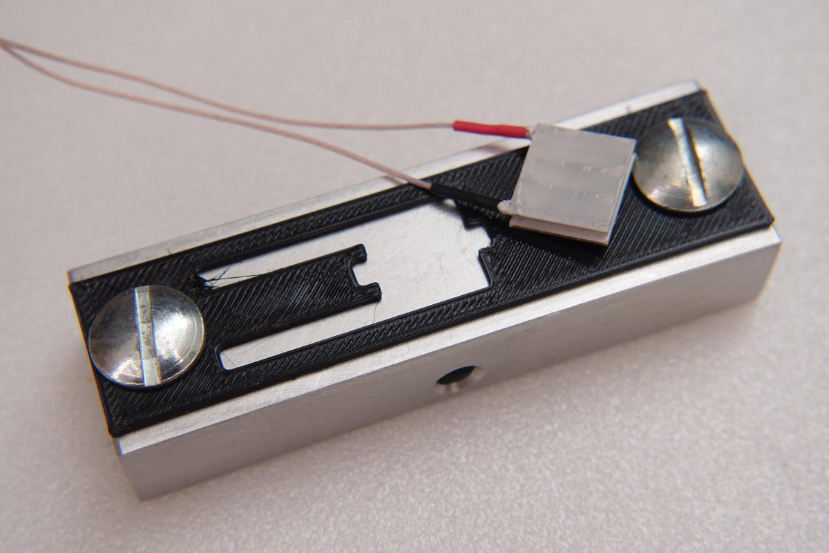
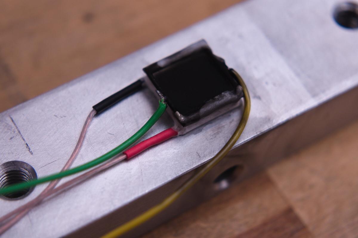
Calibration takes place by heating one side of the peltier element with a couple of SMD resistors. Since they are going to be attached permanently a bit of space has to be left for the light to shine in. Five 100 Ohm SMD Reistors (0804 or 0603) in series and that again in parallel on both sides just about fit on that ceramic. That creates a resistance of 250 Ohm, thus 200 mW of heating power at 7 V.
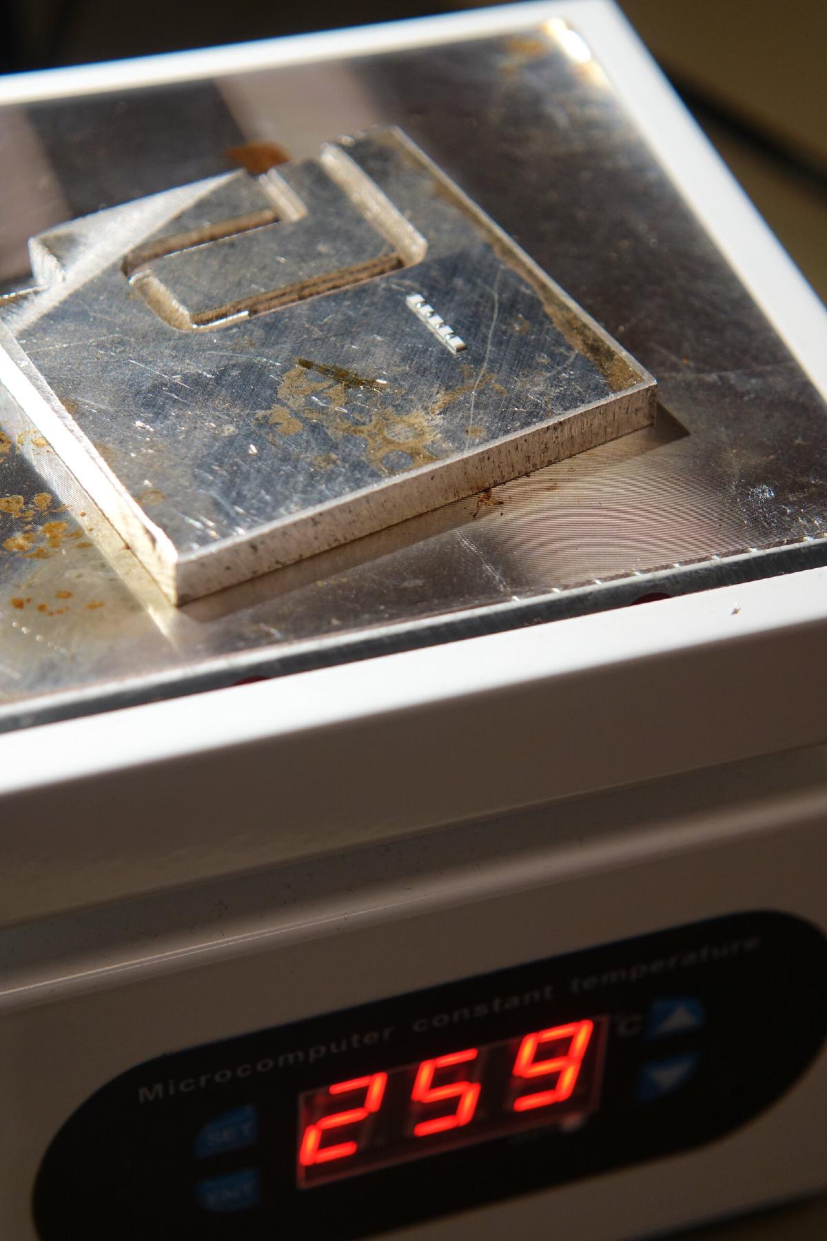
Soldering a few SMD resistors directly onto each other by hand is quite nerve-racking. Just a bit too long and the dust particle sized component falls off the rest of the chain and keeps sticking to the soldering tip. Having access to a hotplate made things much easier. A piece of aluminium as layer underneath the parts, then placing the resistors and adding a tiny bit of fresh solder. With tweezers the next part can be slowly moved to the right place. After all resistors were placed the aluminium plate is carefully moved to another place to cool down. At the same time this method results in a flat underside where the solder is otherwise more of a blob which should result in a better heat transfer to the peltier module.
The peltier module is this one:Peltier-Element TB-65-0,6-1,5, 8,1 V/5,5 W, 13x12x3,25 mm
Going by the product title this on is a very small one with only 13mm x 12mm area.
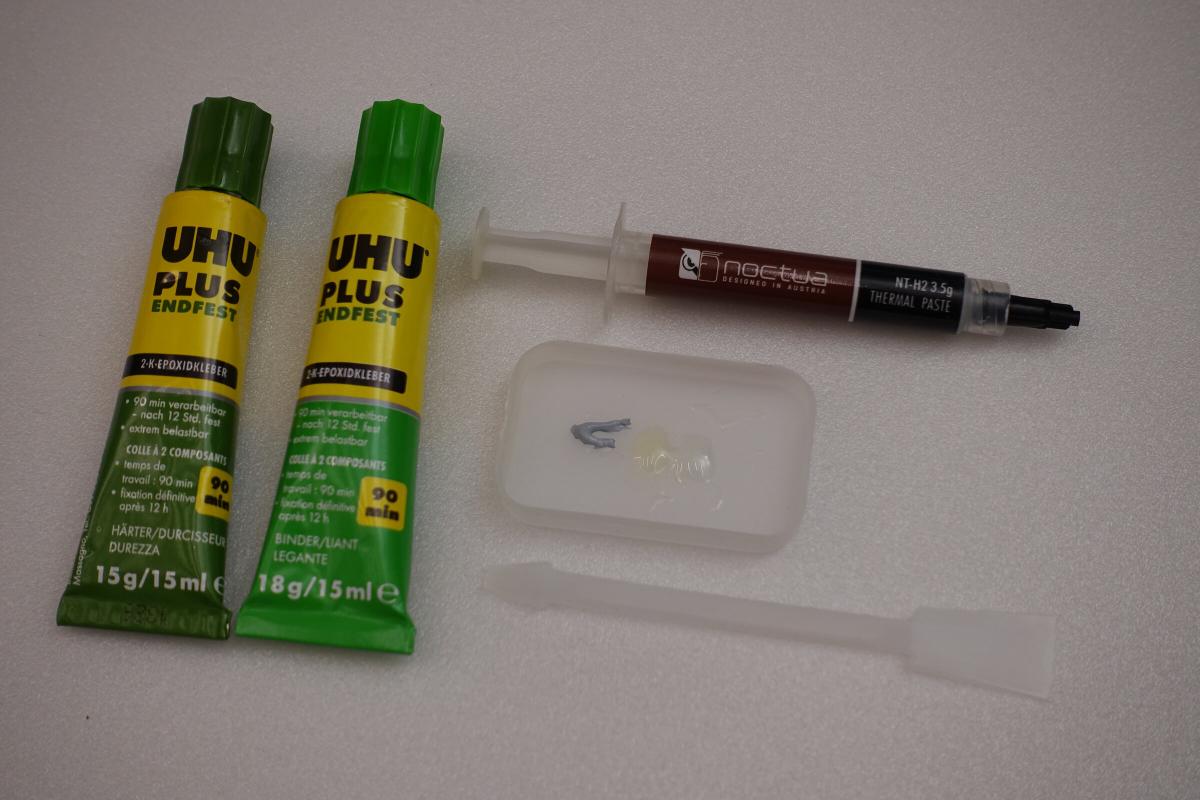
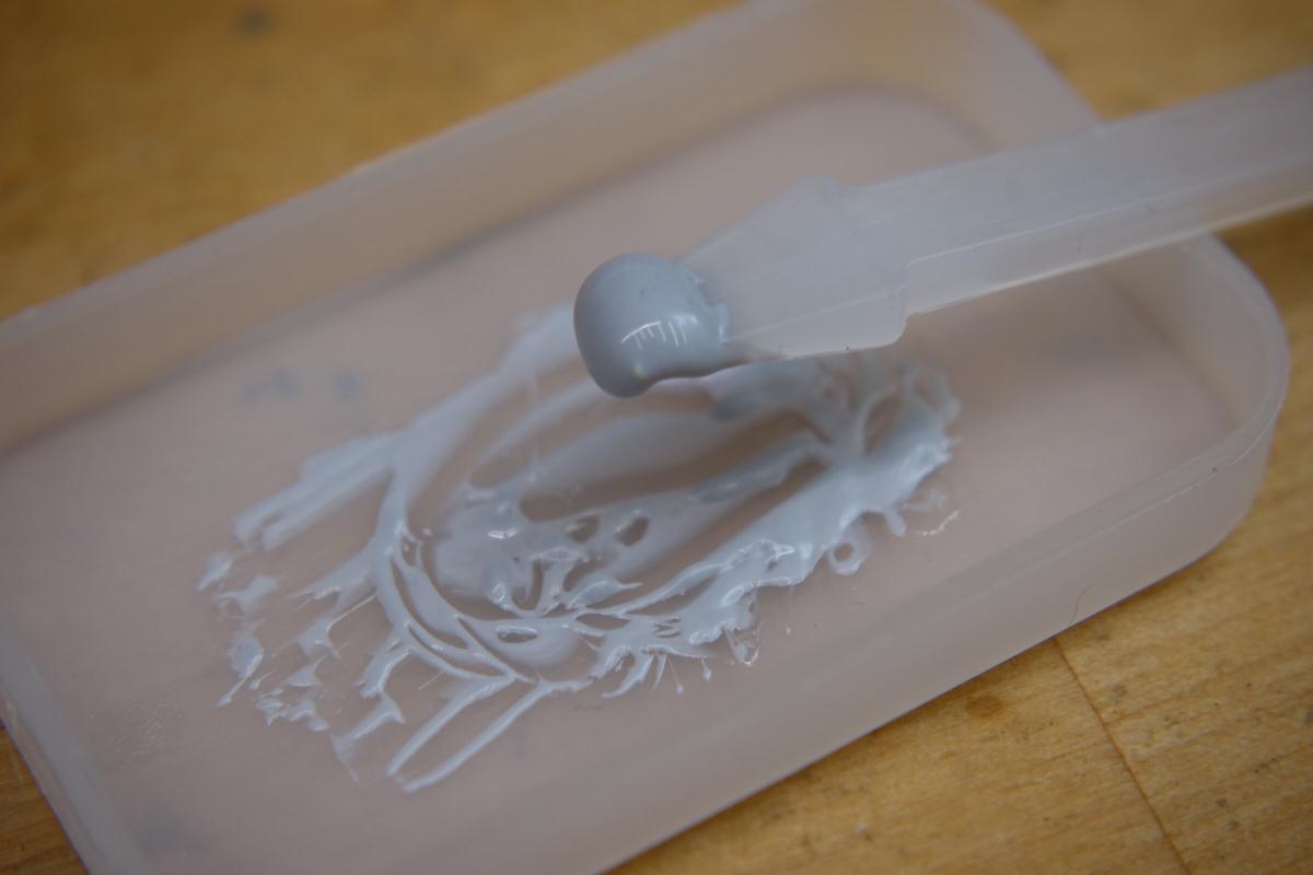
A mix of two component epoxy and thermal paste is used to glue it to the heat sink. With the knowledge gained from a Reddit post “Homemade Thermal Epoxy, Very basic testing” two to three parts of thermal paste added to both parts epoxy glue (so a bit more than 1:1 thermal paste to glue) result in a good tradeoff between thermal conductivity and strength. The resulting resin has after curing a slightly rubbery feel to it. For the low power I am expecting and this being more of an experiment buying a ready made product was not worth it. I did not have to buy anything new for this thermal epoxy.
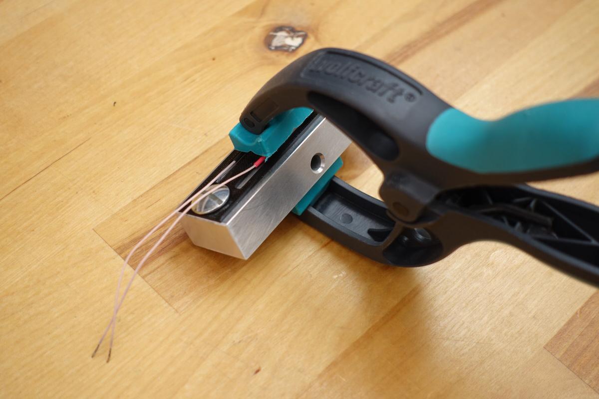
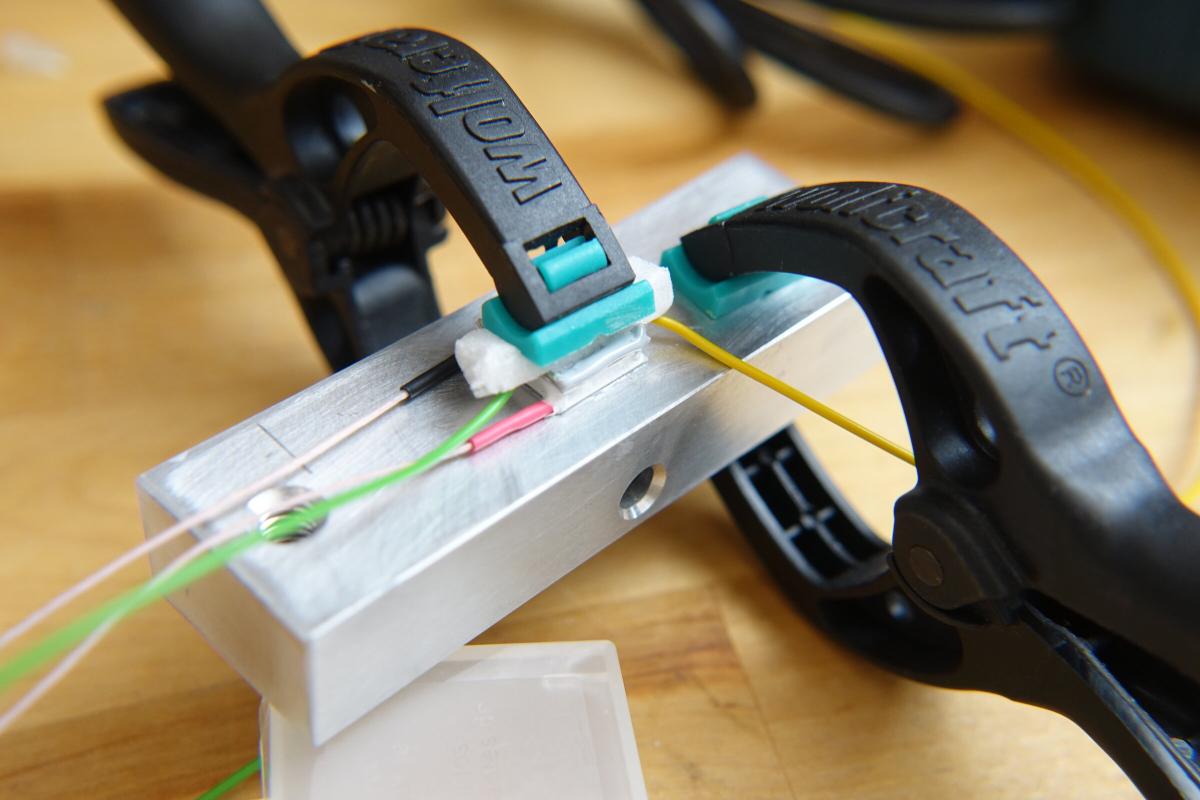
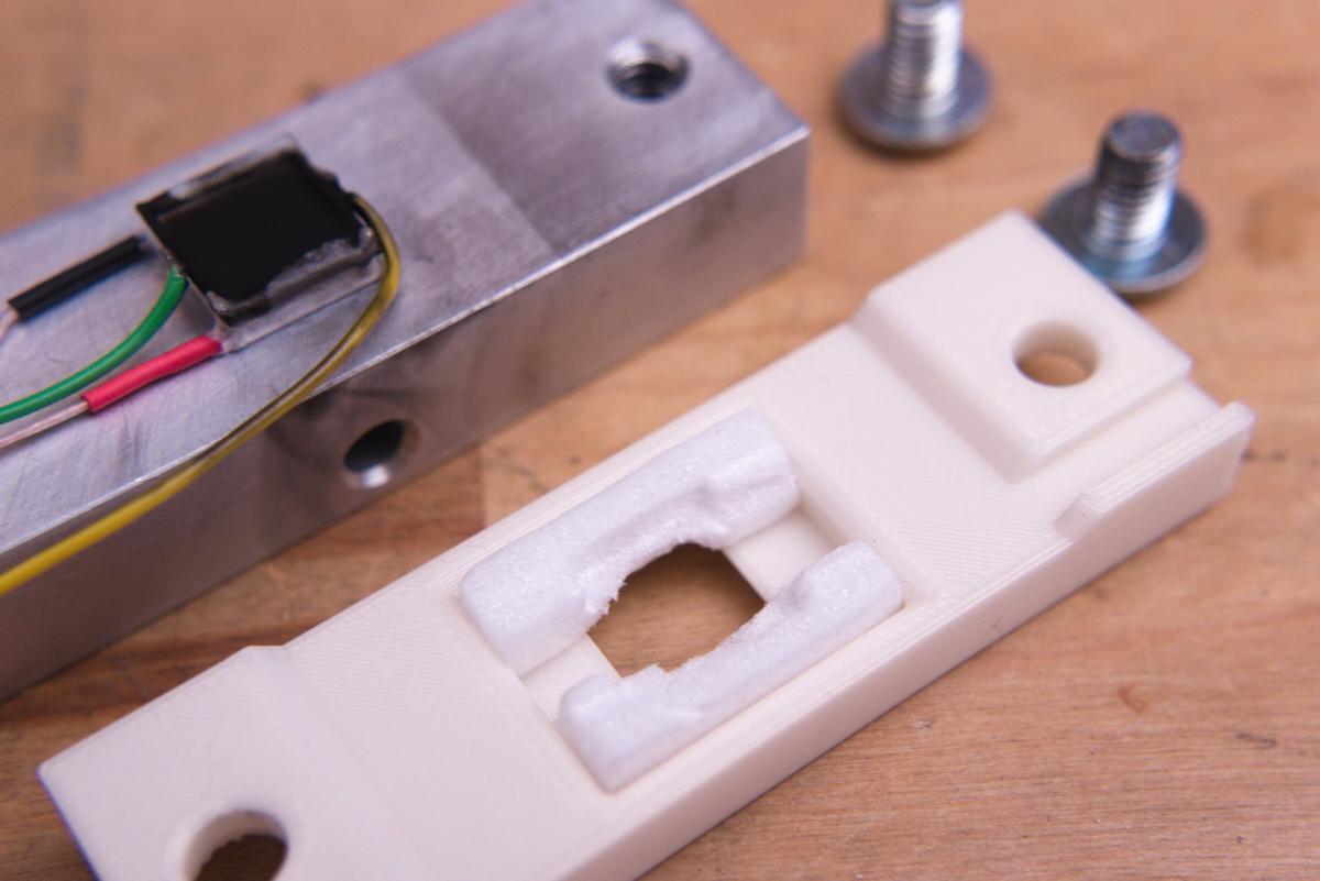
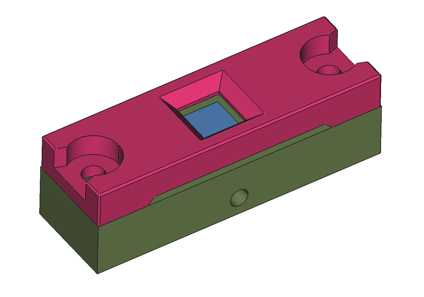
Later I will need to design a cover anyways, so why not printing a alignment jig as well.
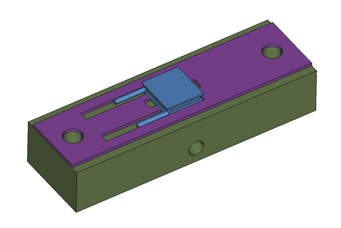
The next day the SMD heating square was glued in place with a second batch of thermal epoxy.
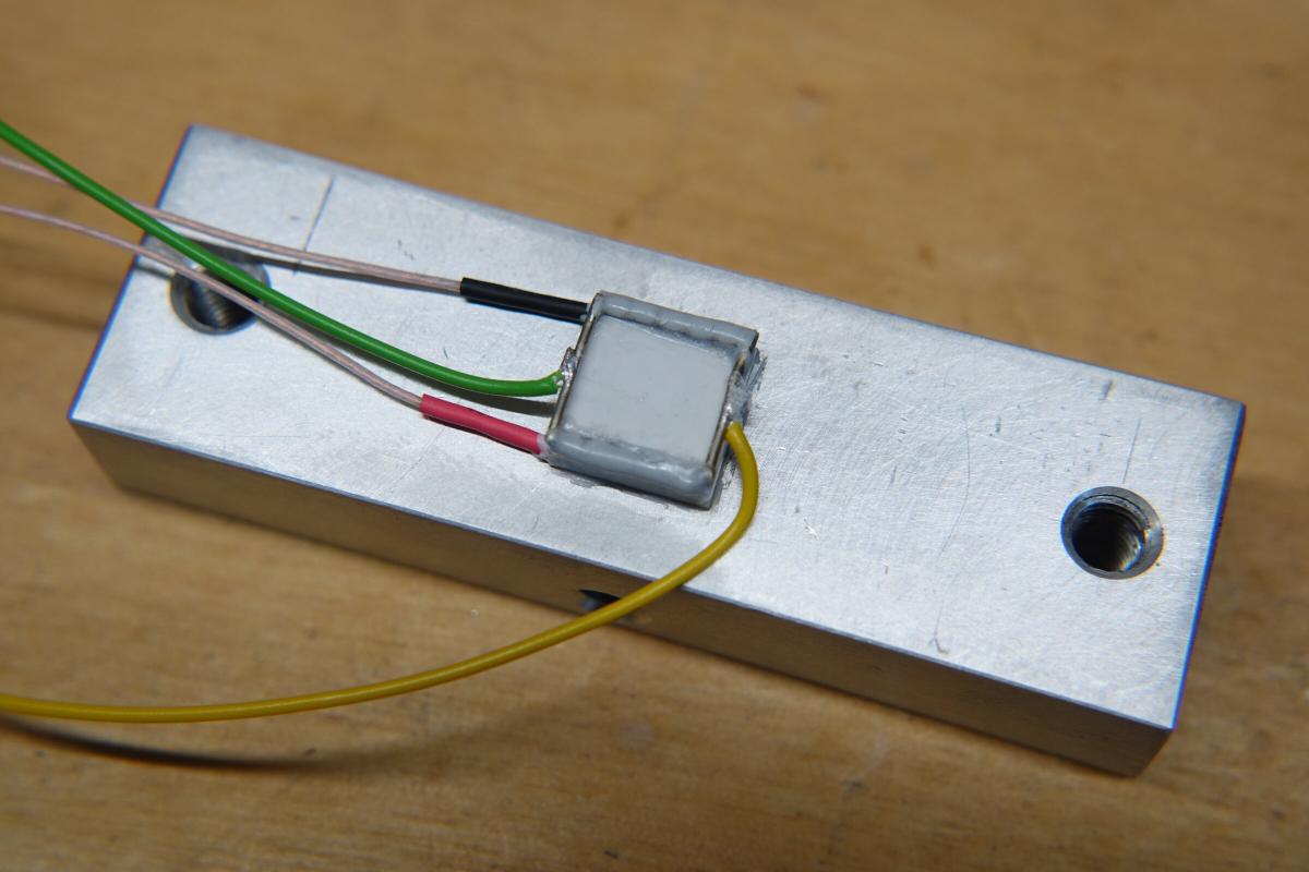
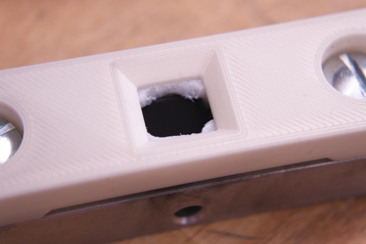
After the voltage at the peltier module is calibrated with the power the SMD heater is giving out the laser pointer can be pointed to the peltier module and heat it instead of the resistive heater. The resulting voltage differential tells us how much power the laser emits. For this to work well enough light has to be absorbed by the surface to heat it up as much as possible instead of reflecting it back into the room. A simple metho is covering is with carbon black (soot from a flame). I recommend trying this out first on a scap piece of aluminium or something similar. The best results I got from holding the part in the center of the visible flame so that is really starts to give off sooty smoke. Holding it shortly (about 10 times each for one second) horizontally into the flame prevents the wires or glue to heat up too much and get damaged. Everything apart from a small square in the middle was taped over with kapton.
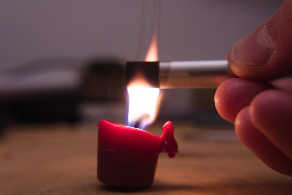
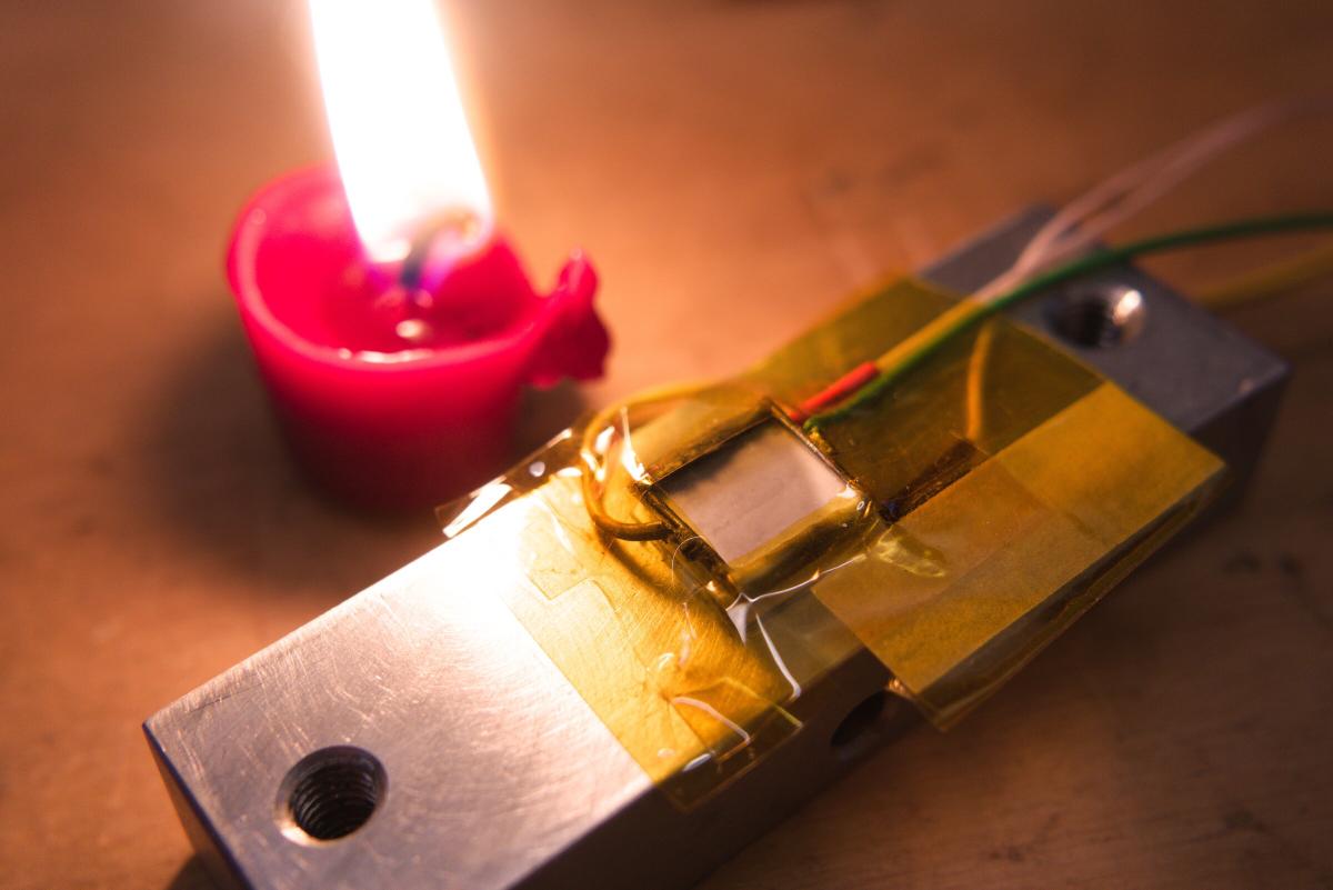
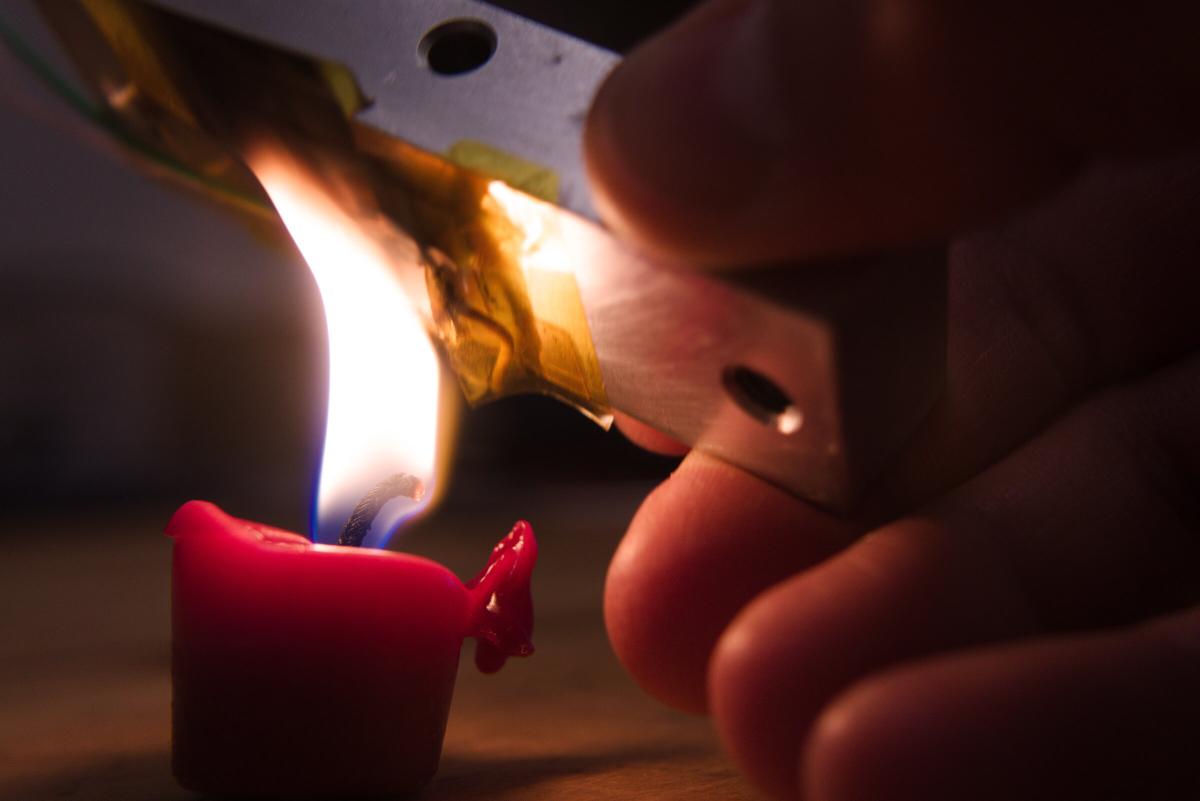
This deep black surface apparently should now absorb 95% of light. Under this assumption the resulting measured power can be divided by 0,95 to adjust for these losses.
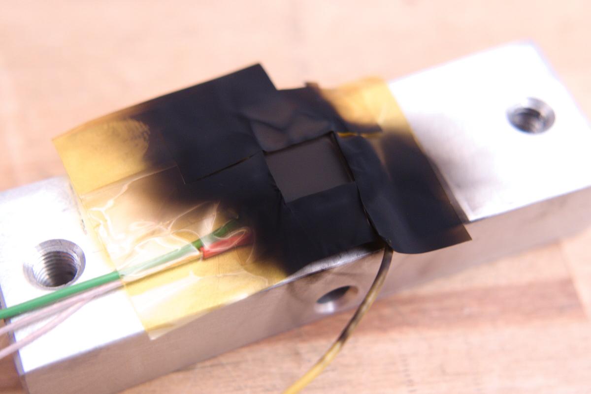
With these low powers air currents do make a measurable difference. To keep these values more stable the SMD heater was covered with a bit of foam. A cover presses that against the peltier module.
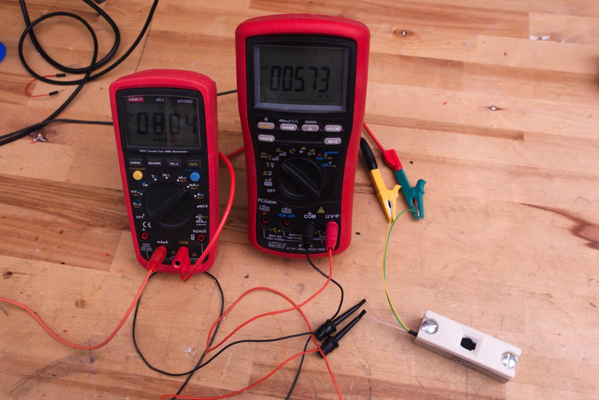
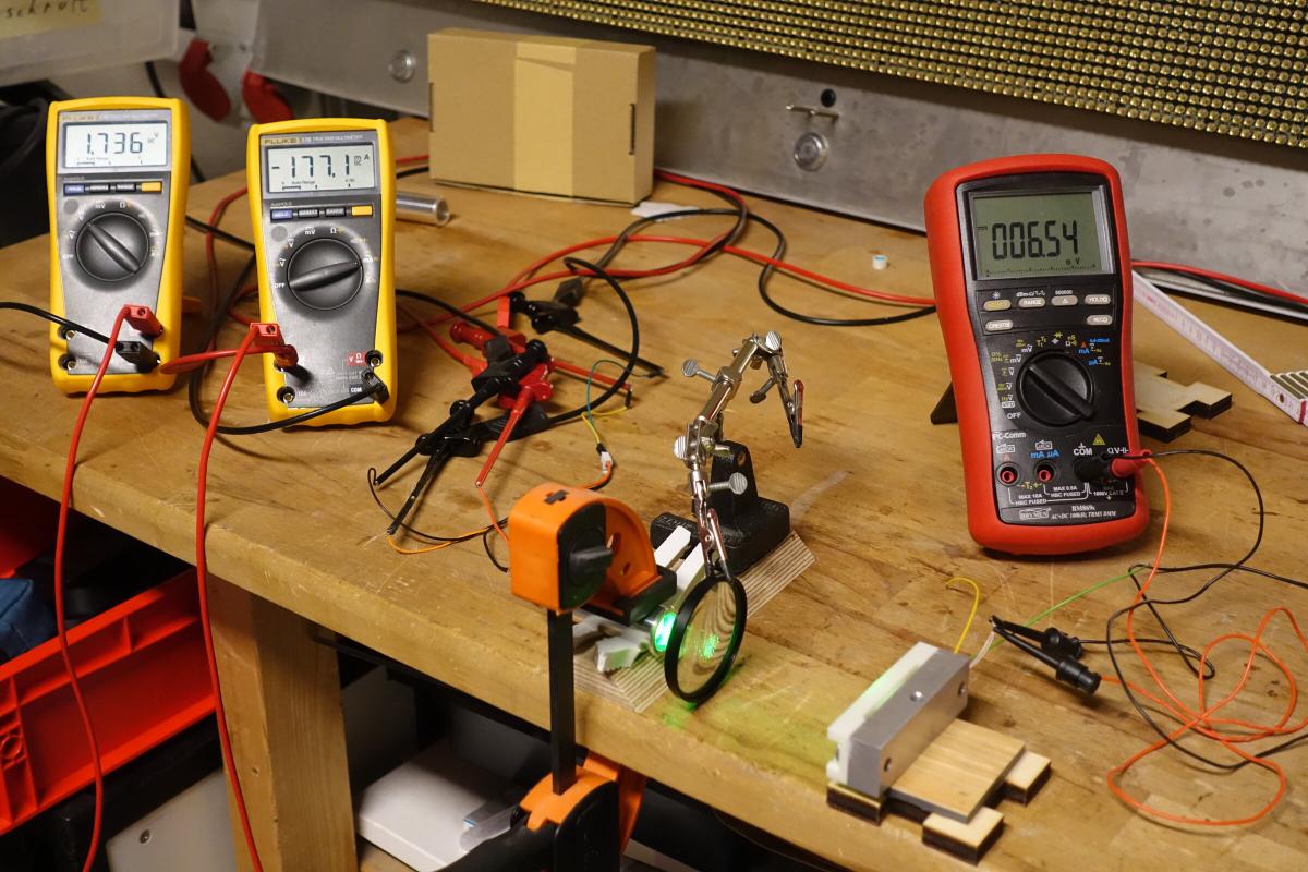
The calibration works as follows:
- Connect the lab power supply to the heater.
- Multimeter in series, to measure it’s current (Scale mA) -> current Heater
- Multimeter in parallel to the Heater (close to the SMD resistors) to measure the voltage since my powersupplys display is not that accurate -> voltage Heater
- This step can be done independently from the next steps either before or after for every selected Voltage.
- Multimeter at the peltier module -> voltage Peltier
- Increase the voltage at the power supply in steps. I’ve chosen 1 Volt increments.
- After changing the voltage, wait for the values to stabilise and note it down.
This table shows the results of my calibration. From the multiplication of voltage Heater and current Heater the Input Power can be derived.
| voltage Heater | current Heater | voltage Peltier | Input Power |
|---|---|---|---|
| 1,0324 V | 0,00409 A | 0,00079 V | 4,222516 mW |
| 2,0215 V | 0,00804 A | 0,0057 V | 16,25286 mW |
| 3,0132 V | 0,01201 A | 0,01364 V | 36,188532 mW |
| 4,007 V | 0,01599 A | 0,02495 V | 64,07193 mW |
| 4,9976 V | 0,01996 A | 0,03915 V | 99,752096 mW |
| 5,985 V | 0,02392 A | 0,0566 V | 143,1612 mW |
| 6,977 V | 0,02788 A | 0,07726 V | 194,51876 mW |
| 7,966 V | 0,03184 A | 0,10126 V | 253,63744 mW |
| 8,958 V | 0,0358 A | 0,12845 V | 320,6964 mW |
| 9,952 V | 0,03978 A | 0,15925 V | 395,89056 mW |
| 10,945 V | 0,04375 A | 0,1932 V | 478,84375 mW |
| 11,937 V | 0,04772 A | 0,23018 V | 569,63364 mW |
If we plot voltage Peltier on the X-Axis and Input Power on the Y-Axis one can admire a wonderfully straight line of which I will probably still dream tonight. The slope is approximated at 2.48 . Assuming an absorptance of 95% the factor is calucated to be 2.6 Watts per Volt.

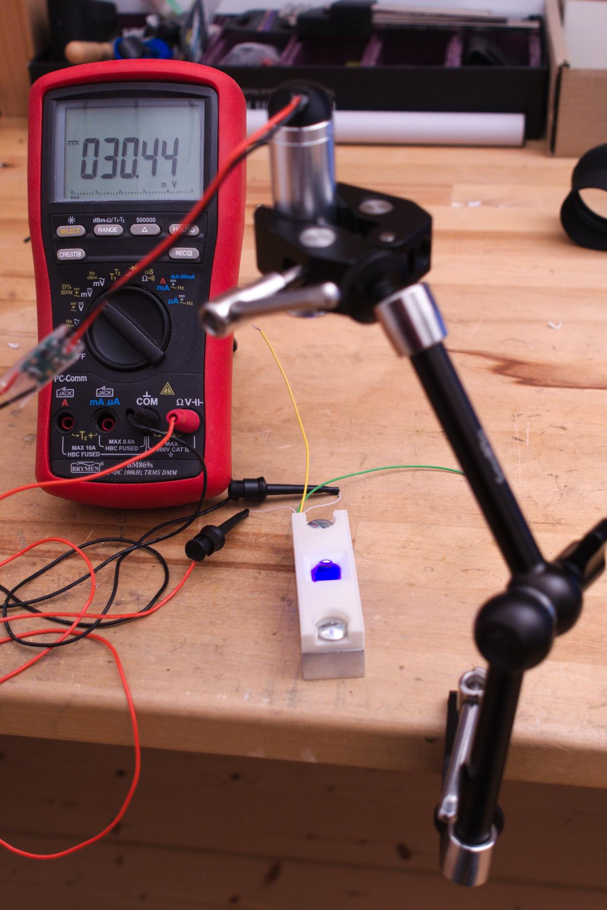
After this calibration we can finally measure laser power. For this we need to disconnect the heater from the power supply. Then pointing a laser to the black surface and maybe defocus it slightly. Reading the voltage off of the peltier module after is got steady enough and then multiplying this by 2.6 W/V.
First measurements showed for example that a 405 nm Fat Beam Laser with its stock current settings puts out 30mV * 2.6 W/V = 78 mW.
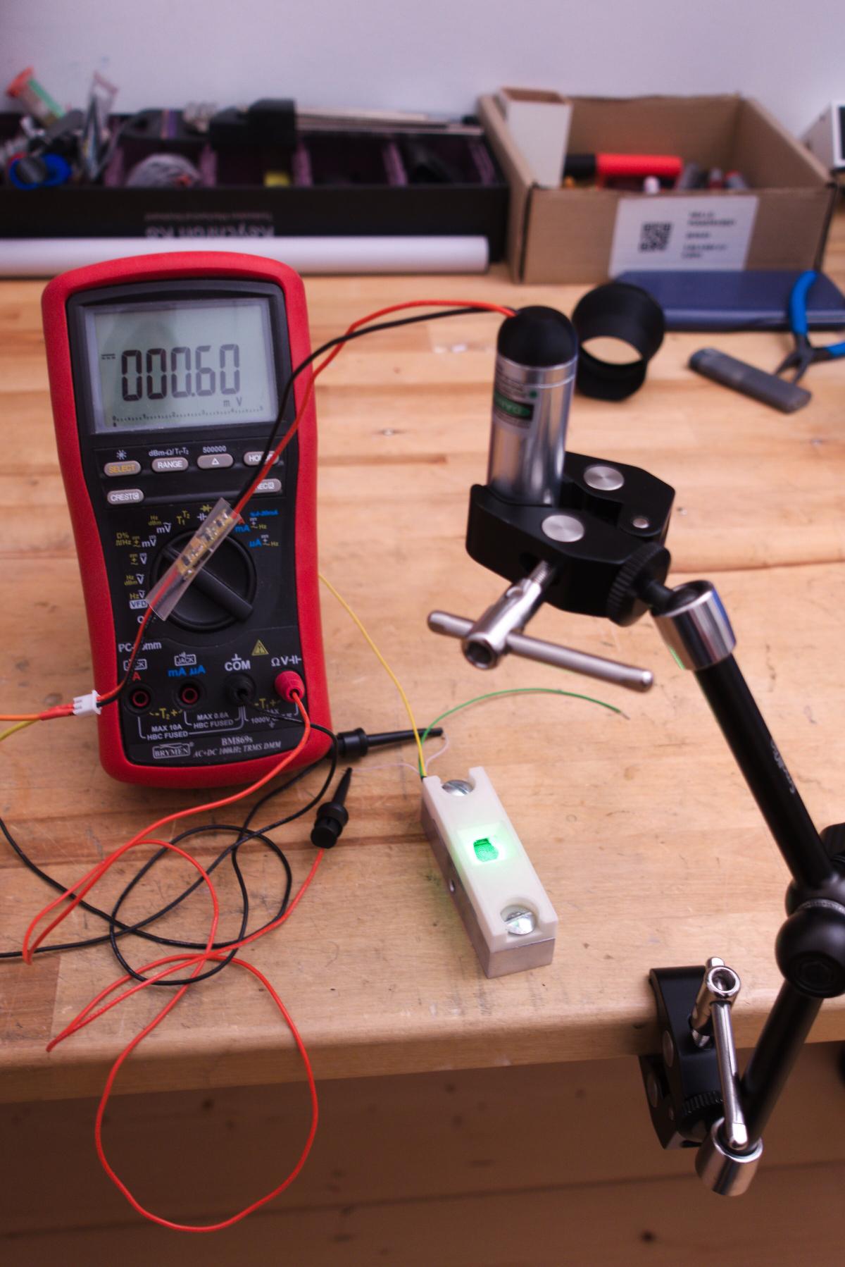
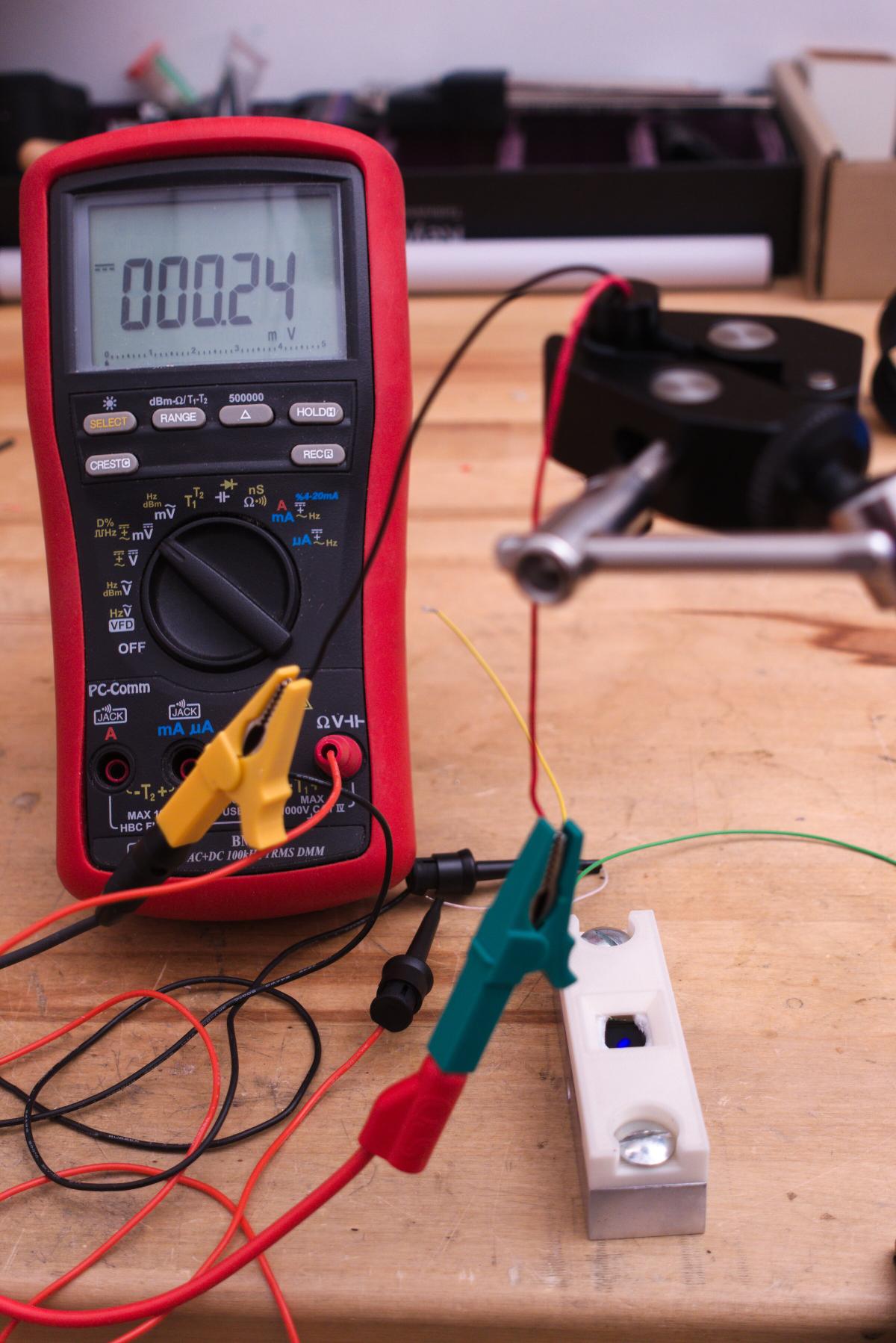
A green Fat Beam Laser, which I already turned down in power, was only 0.6 mV * 2.6 W/V = 1.56 mW.
And another 405 nm dot laserpointer got up to 0.24 mV * 2.6 W/V = 0.624 mW.
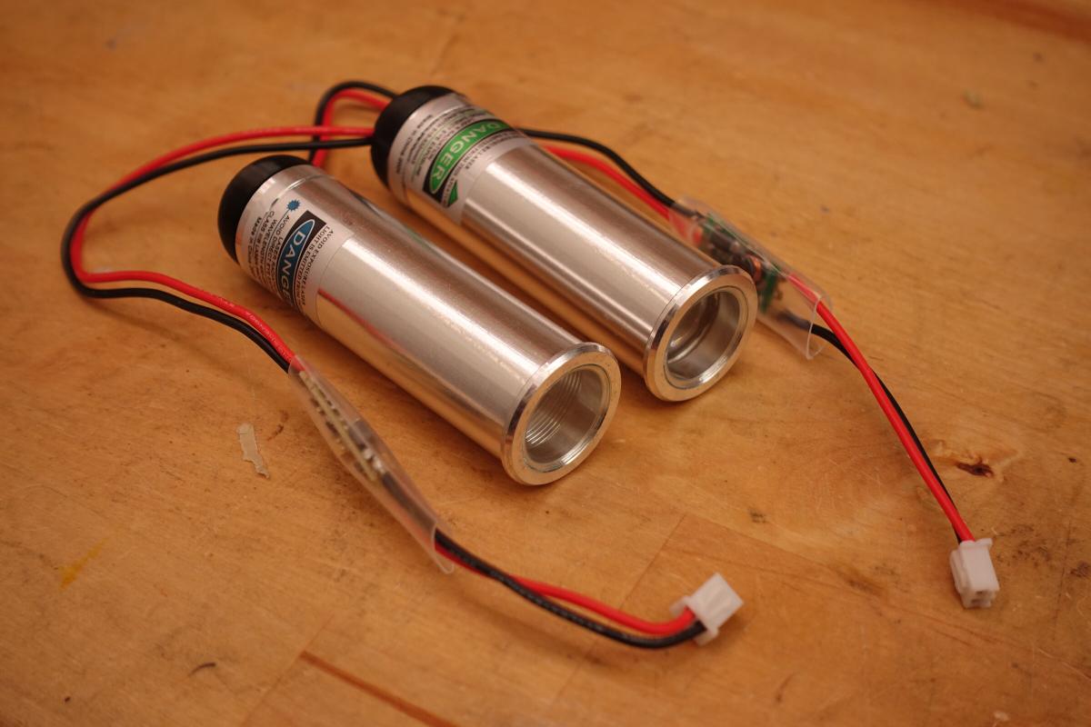
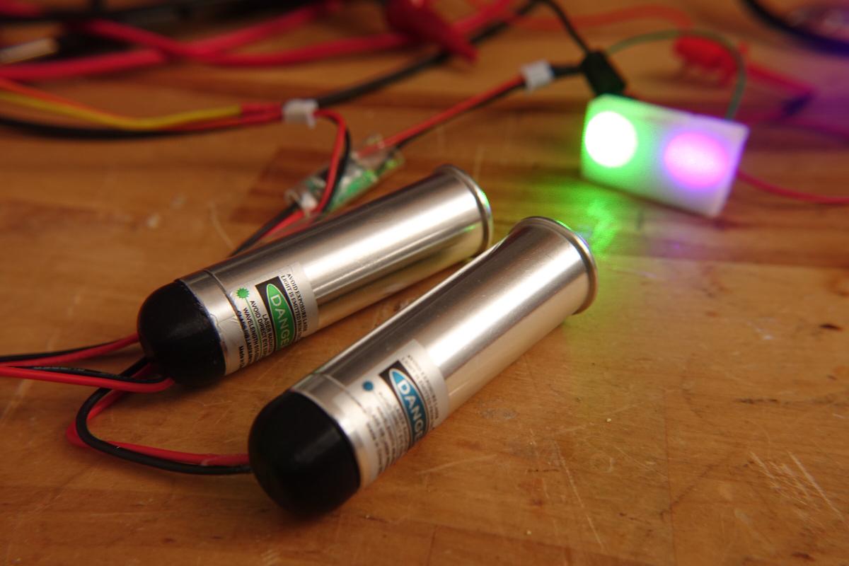
Fat Beamer Laser Measurements
For the modified PTZ camera I bought two Lasers, one with a purple beam (405 nm) and the other with a green beam (532 nm). The power was specified with 250 mW (405 nm) and 50 mW (532 nm). In front of the diodes is a lens attached, which results in a constant dot with about 1 cm diameter.
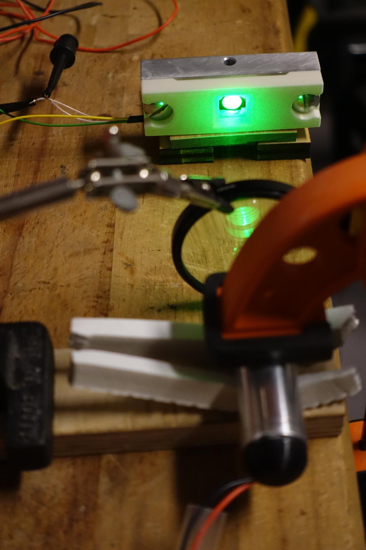
In line with the cable is a small PCB with a potentiometer to adjust the power. By using the just build power meter it was possible to measure the actual light power output and to compare it against the electrical input power. The laser module and the sensor was attached to a table. The laser beam had to be focused just a bit by use of a lens to fit on the small peltier element. Step by step I adjusted the potentiometer and after the voltage had settled I noted it down together with the voltage at and current to the diode.
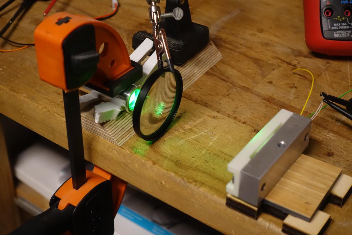
Besides the green and purple/UV laser I also mounted an IR cut filter from a camera in front of the green laser diode, because apparently cheap diodes send out IR light as well.
The following graph shows the results of those three measurements. Getting plausible readings at lower powers was not really possible. I therefore had to skip them.

In general one can notice a pretty linear relationship between electrical an optical power. The differences on the lower values come from the measuring inaccuracies resulting from for example changes in temperature and air currents.
Also the use of an IR cut filter shows an effect. Here I can only conclude that about 35% light gets absorbed. How much of that is acually in the infrared spectrum I cannot tell.
Files:
CAD Modelle: git.ctdo.de/interfisch/laserpowermeter/src/branch/master/cad