Project start: November 2017
Language: German, English
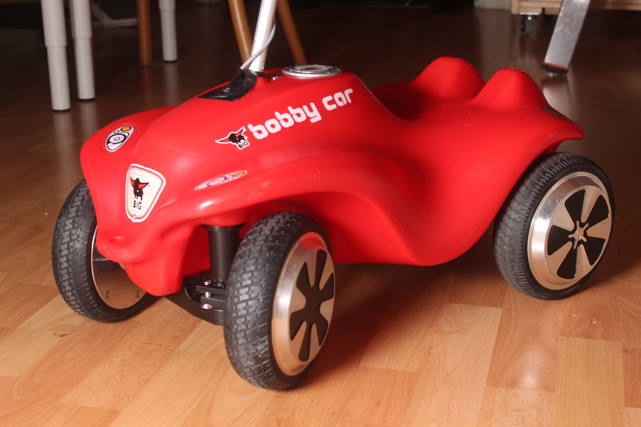
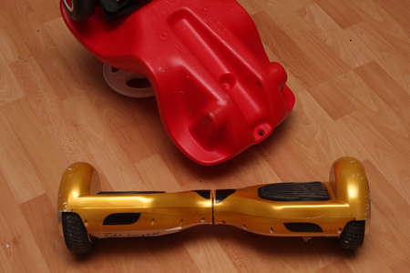
E-Bobby Car
Lately we got a bunch of broken Hoverboards and some unchecked returns.
One of those I repaired to drive on myself, the rest will be used for great things.
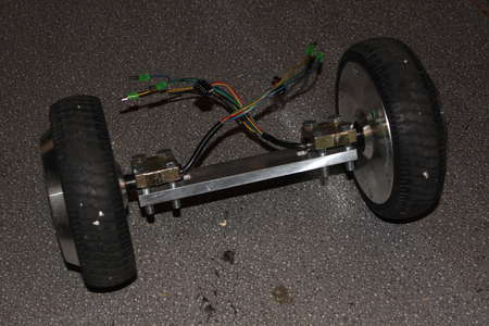
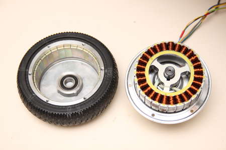
With these Hoverboards / Balance Scooter the motors are inside of the wheels. Therefore no complicated mechanics are needed to build something the drives.
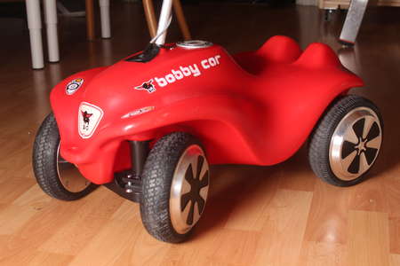
One day I was holding one of the salvaged wheels the Bobby Car came to my mind. So I asked myself if this would fit right underneath. It did, otherwise you would not read about it here.
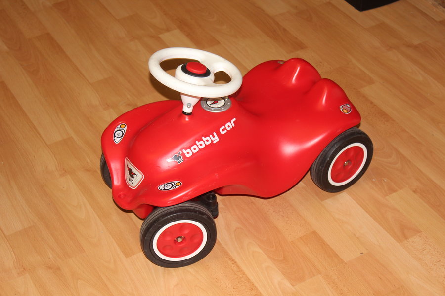
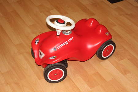
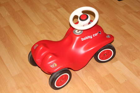
I got the BIG Bobby Car locally via ebay. The woman said to me "have fun", as if she knew what I had in mind.
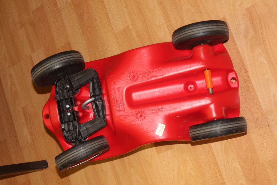
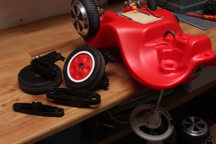
Well, pictures. From the left, right, above, under, ...

Of course I did some research first if they would fit. The wheels of a hoverboard, at least the smaller ones, are 6.5" in diameter, thats 1cm bigger than the stock Bobby Car ones.
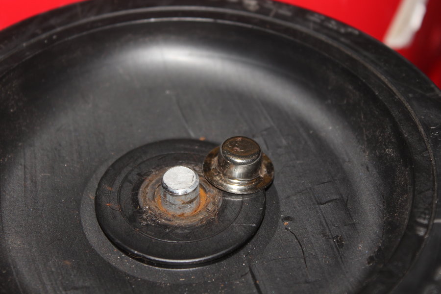
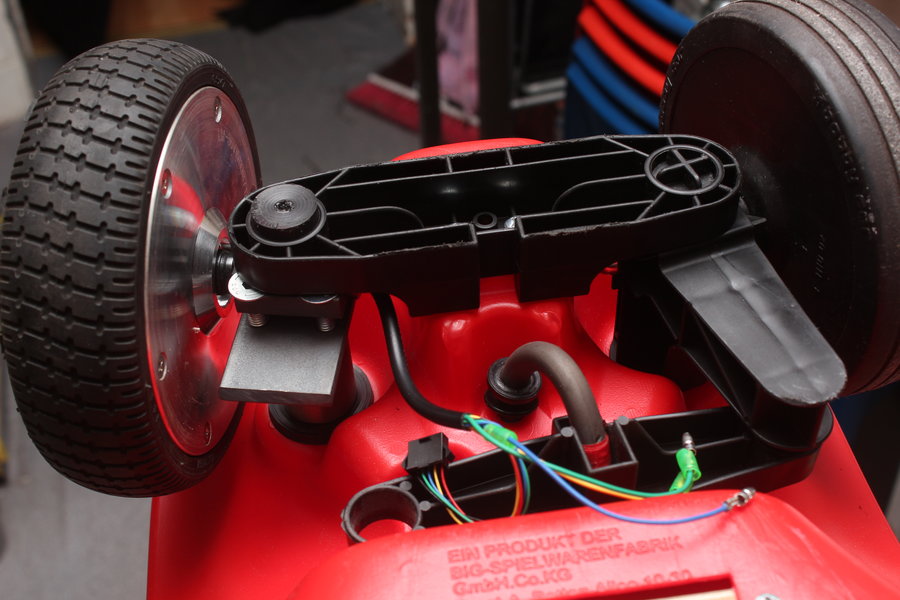
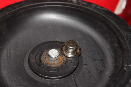
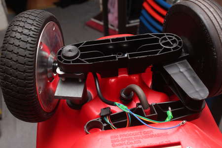
To get the rear wheels off of the Bobby Car the metal cap has to be taken off on one side. For this I recommend pressing the cap to an oval shape with pliers in such a way, that the two clip thingies are no longer held in the groove of the axle.
After that the metal rod can be pulled out and both wheels are free.
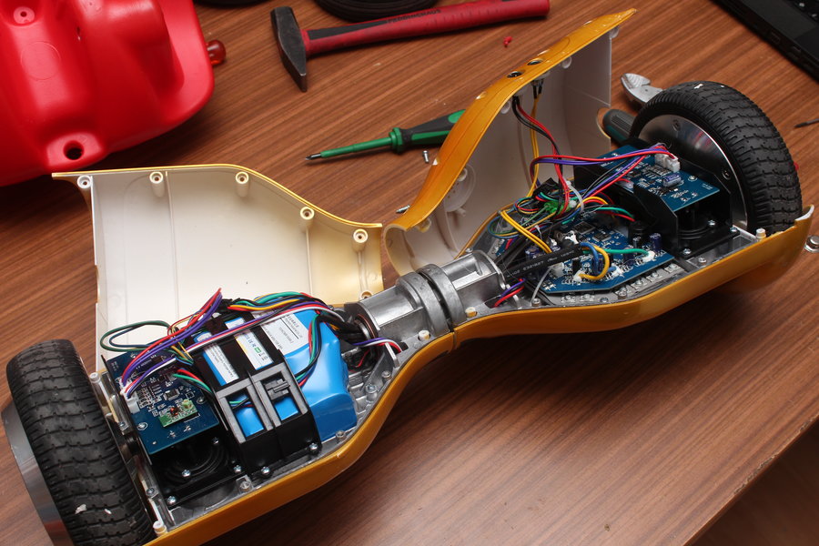
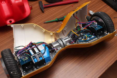
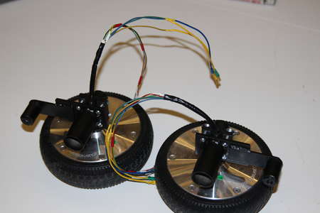
Here you can the see the Hoverboard from where I'm going to salvage some innards.
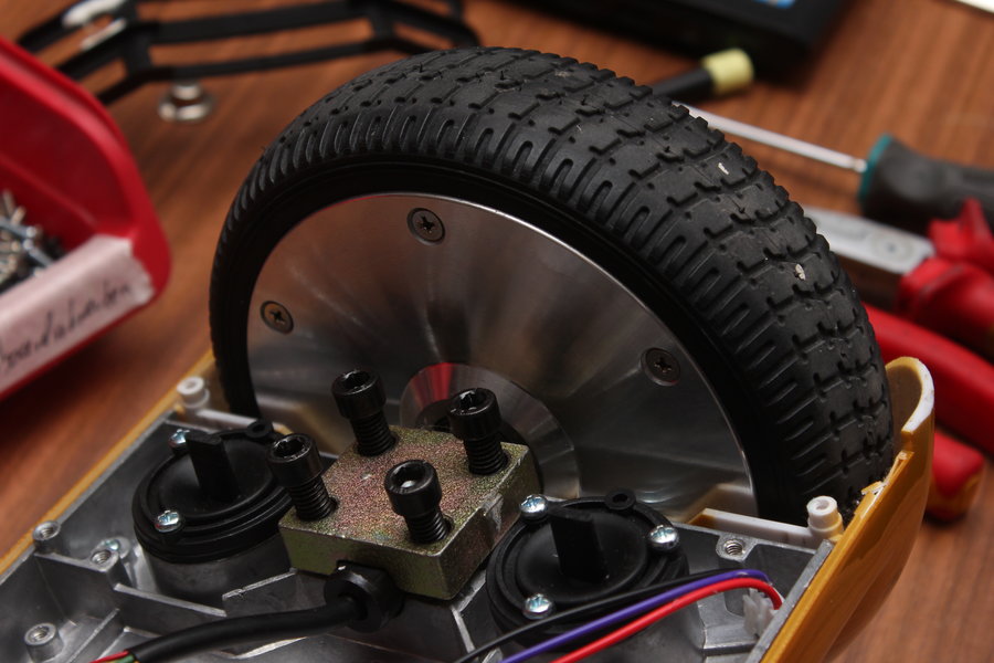
A short digression, for those who haven't seen one from the inside: On both outer end are the wheels located.
The motor is of a brushless kind. Motor wires and the wires from the hall sensors come through shaft. The shaft has a noth and is held down by means of a metal plate and four thread screws.
Looking at the pictures the mainboard can be found on the right half of the mainboard. It uses an STM32F103 to implement two brushless controllers.
On the other side the 10S2P LiIon battery with built-in BMS is located. The two similar looking pcbs next to the motors contain an IMU each to control the hoverboard, therefore each side is balanced independently.
Charge controlling (CC/CV) is done inside of the power supply bricks that come with it.
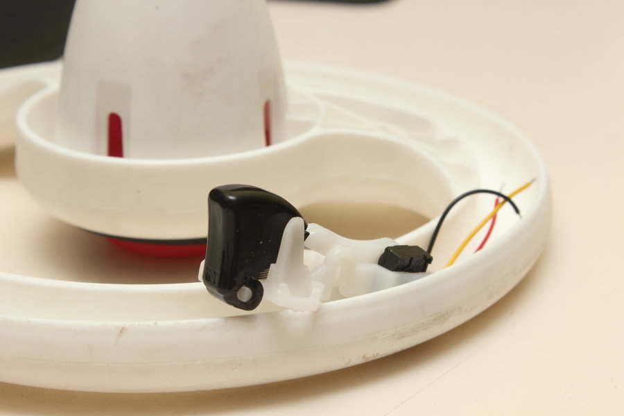
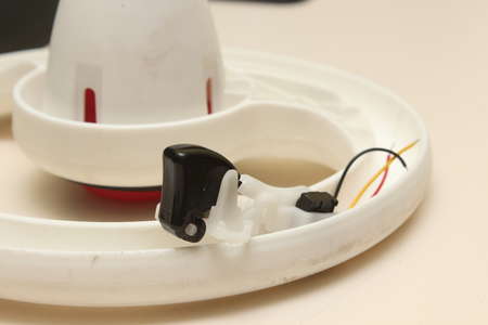
Once someone steps on the Hoverboard at least on of the two rubber pegs is pressed down. This is then detected by a light switch which activates the controller. Simple stuff.

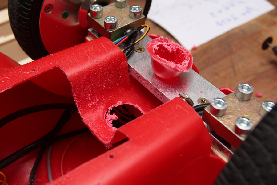
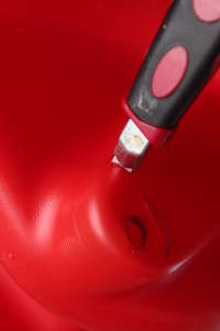
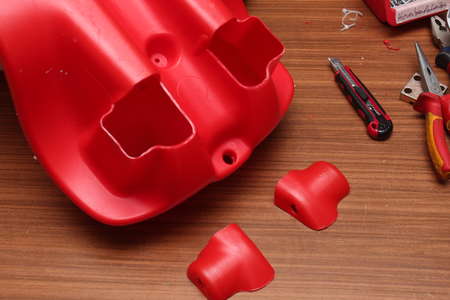
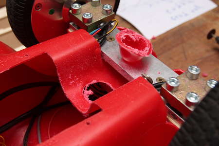
This bit of plastic will never withstand the force of the motors. Besides that there would be no place to attach the shaft.
To fix that I cut out two corners with a box cutter.
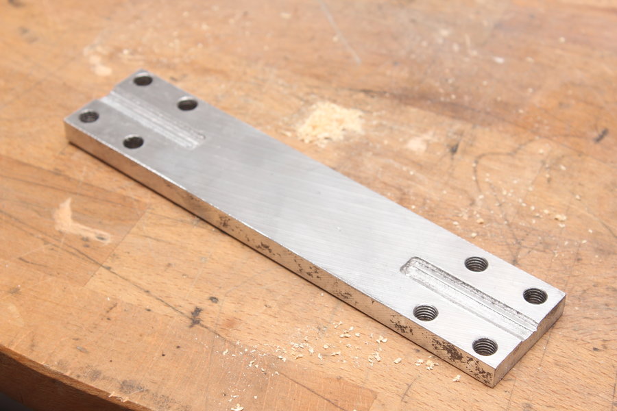
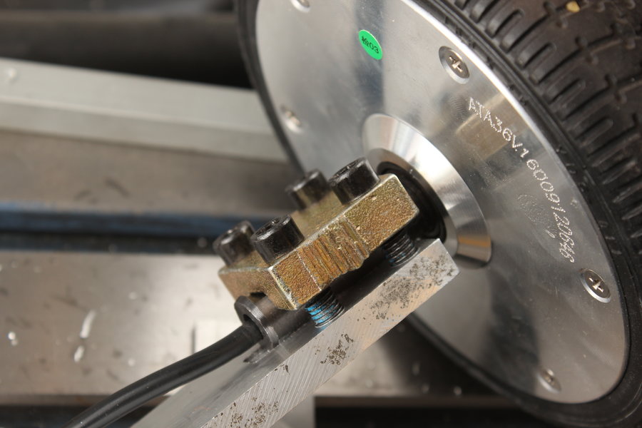
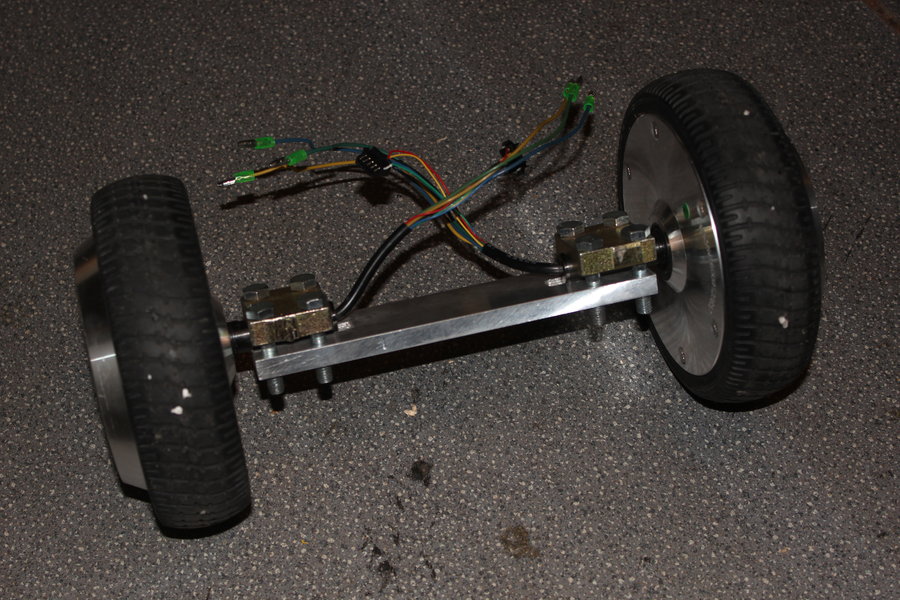
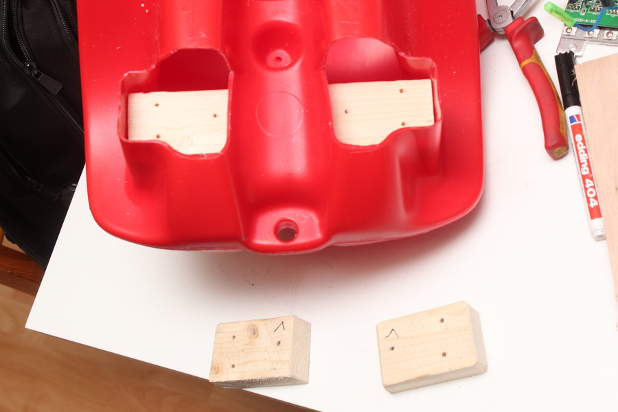
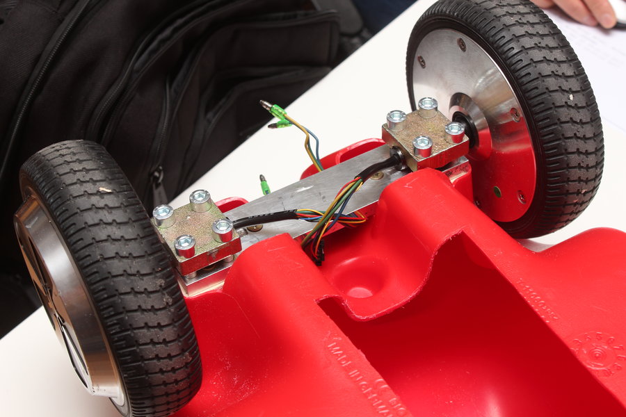
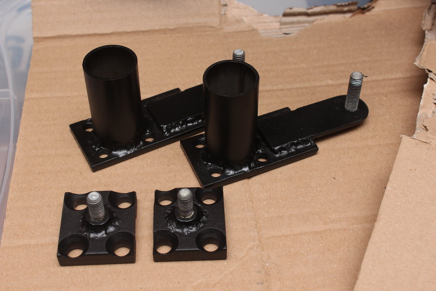
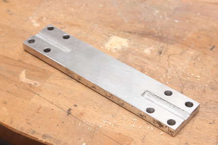
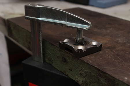
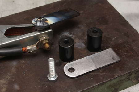
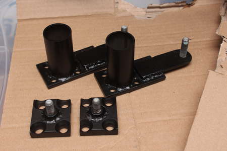
To keep the wheels from twisting I mounted them to a 1cm thick aluminium bar. The short thread screws were later replaced by better fitting 30mm long M8 ones.
The hole spacing is btw 24mm by 30mm.
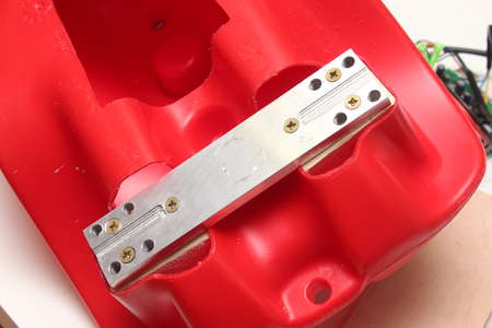
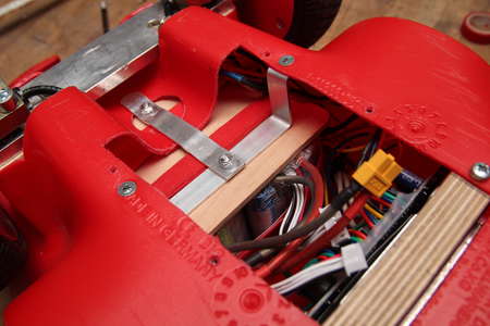
I did a lot of thinging on how to attach the aluminium bar to the bobby car.
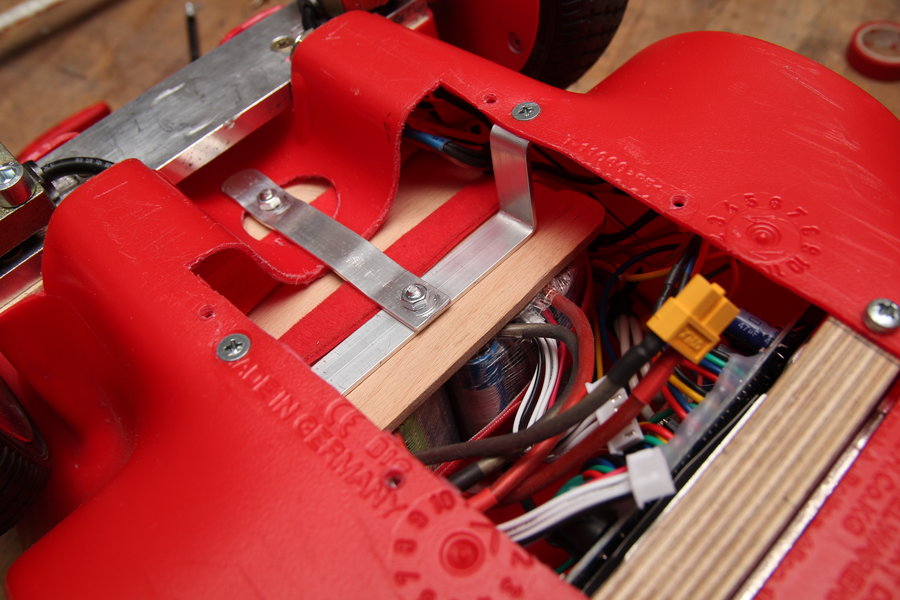
Eventually a long piece of wood was sitting inside the chassis. Two wooden blocks were used as spacers. Finally six wood screws clamp the aluminium bar to the plastic chassis.
We'll find out if this needs reinforcement. Until now it held up well enough.


Of course the hoverboardmainboard should not balance something anymore. An
alternative firmware makes it possible to reuse both ESC's.
I used the
fork from NiklasFauth and flashed it to the STM32F103 with a ST-Link V2.
First I tried using CPPM with a Frsky DR4-II, which did not work that well because of signal issues. Controlling via UART on the other hand worked better.
Instructions on how to flash the firmware can be found under
Firmware Hack.

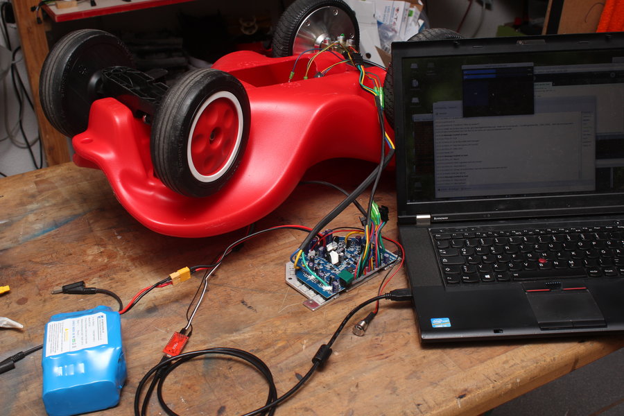
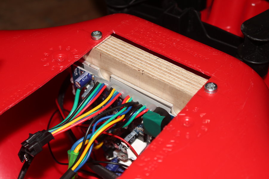
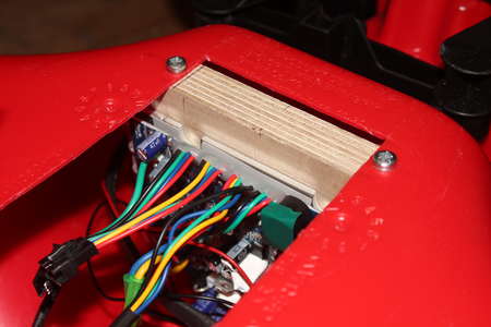
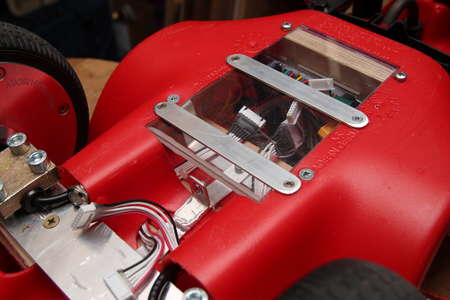
The Bobby Car is very empty inside. Still I spend quite some time thinking about how two Hoverboard mainboards (the second one will be for later four wheel drive) and a battery would fit best.
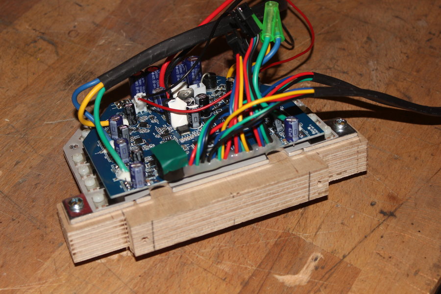
Eventually I screwed the mainboard to a piece of multiplex wood which will then be mounted vertically at the front part of the cutout.

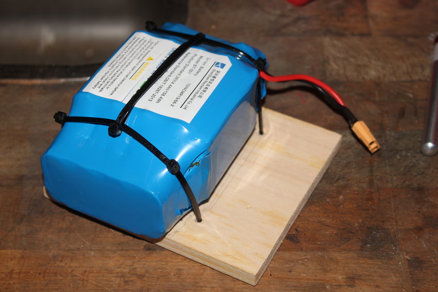
The batterypack is attached to a wooden plate with some zipties. This will then be used to close the opening.

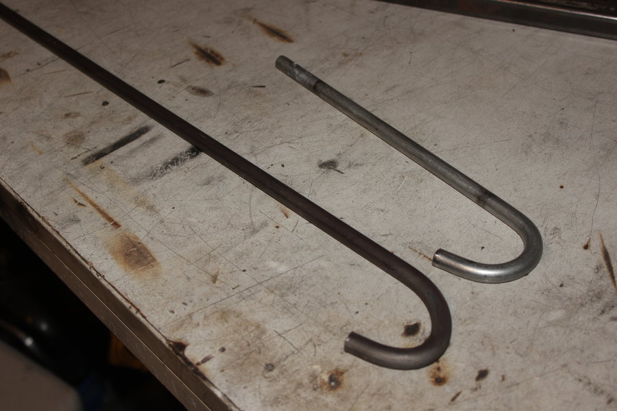
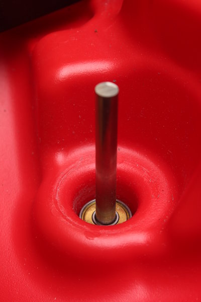
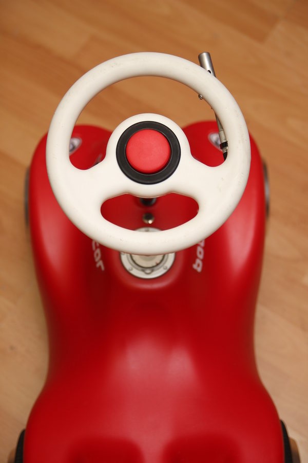
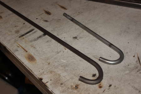
One thing that definitely had to be changed was the steering shaft. With the height is was until now it is not possible for a normal sized adult to steer.
So I bought a steel rod with a diameter of 10mm and bent one end to a hook shape, similar to the original shaft. Without knowing the best length I made generously 15cm longer, which turned out to be perfect.
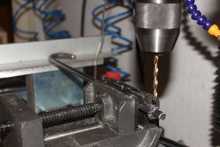
At the top end a 4mm hole had to be drilled to lock the steering wheel into place again.
The last thing missing was a way to accelerate. First I thought about building a thumb throttle with a hall sensor, but this would be mechanically too complex for now.
Luckily I found a broken XBox One controller with an analog shoulder key. During the 34C3 I managed to connect the throttle to the mainboard.
The test track of our Chaos West Assembly was perfect to test the Bobby Car. There I noticed that the front wheels have no grip on the floor of the exhibition hall of Messe Leipzig and that steering above 10km/h is not possible.
Also the slide bearings of these front wheels do get very hot after just a few minutes of driving.
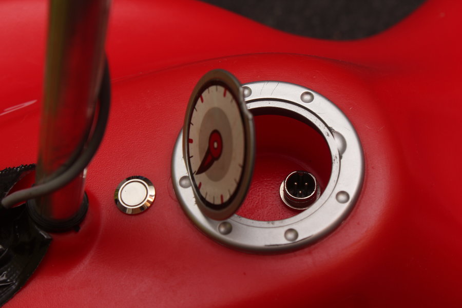
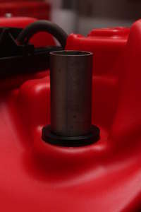
Now only the power button and a charging port had to be put in. The latter is reasonably placed right under the fuel tank cap.
Even though these shortcomings it was not only for me, but many others a great fun driving the Bobby Car so I am definitely going to exchange the front wheels for those of a Hoverbaord.

Front Wheels
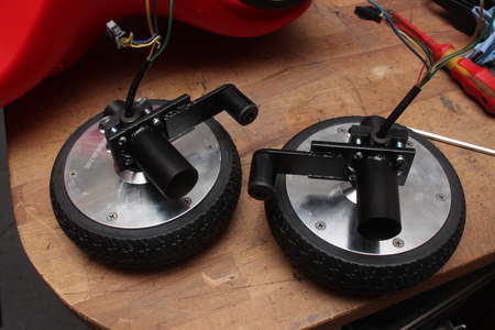
Hoverboard wheels are also well suited as front wheels. Alone for their ball bearings and rubber tires, not to mention the builtin motor. Wiring those up as well is not that much work, four wheel drive, yay \o/
The steering relevant parts are made out of plastic, as well as the wheels which rely on the low enough sliding friction between steel and plastic.
Only two tapping screws are used to keep the upper bracket in place. After taking off this part the rest falls apart by itself.
The steering axles are also just resting on the plastic body of the Bobby Car. Here I can't see any wear so I will rebuilt it in the same way.

A 608 skate bearing does actually fit inside where the steering axle used to sit.
There the ball bearing should only absorb the side forces.
The load applied by myself will be taken by a turned POM bushing.
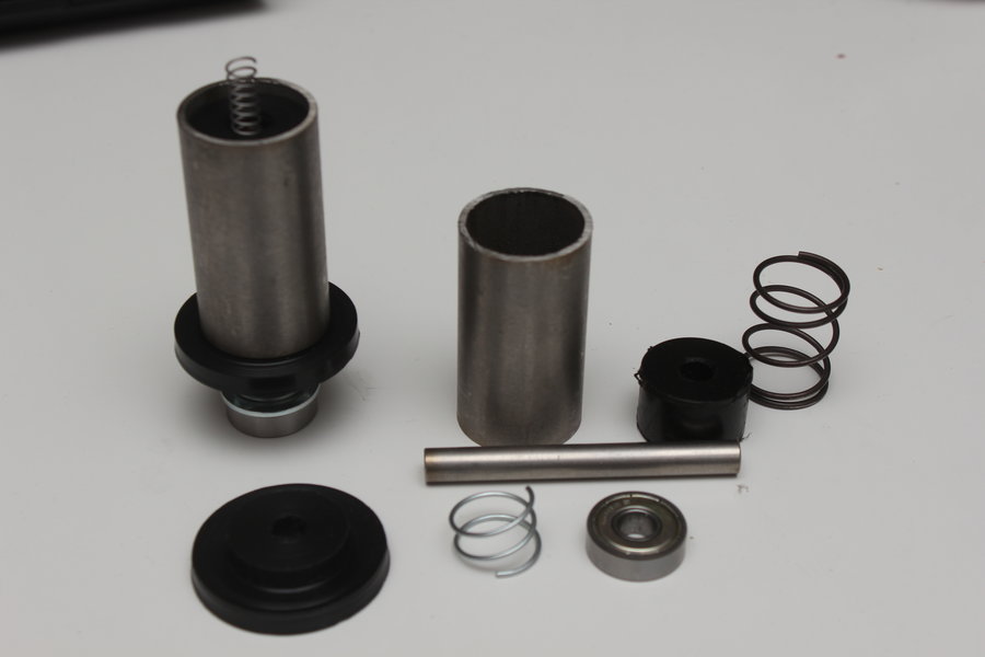
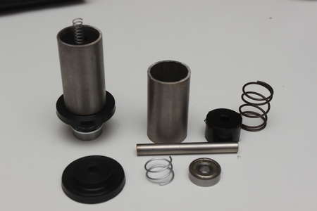
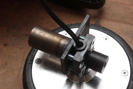
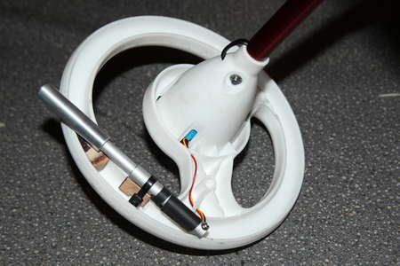
The shaft of the hoverboards wheels has to intersect the rotational axis of the steering axle. Because the wheel shaft has to be held down somehow this was not as simple as it was with the stock wheels.
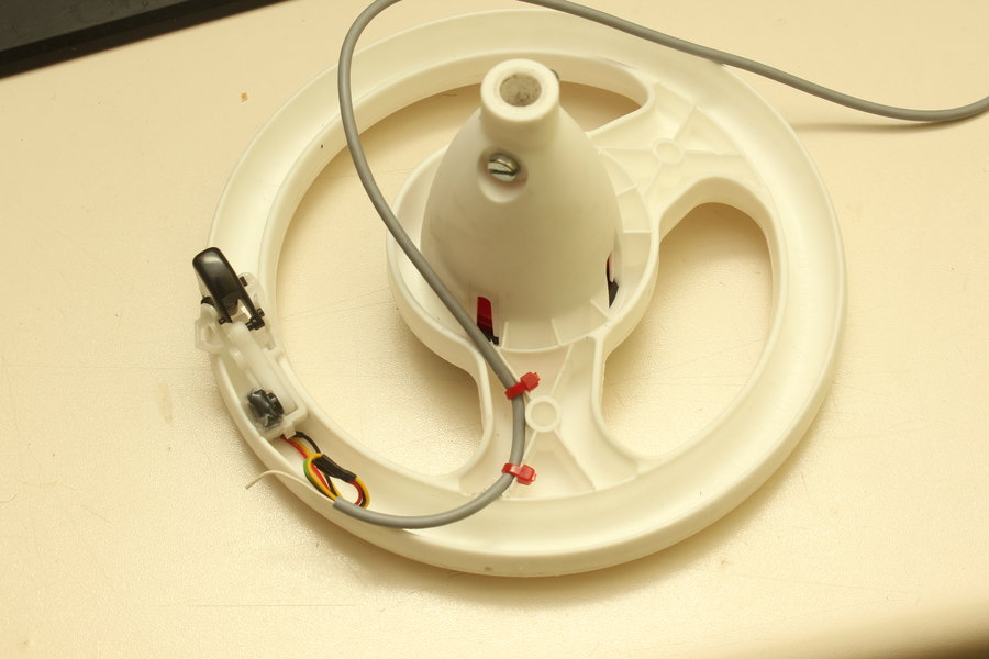
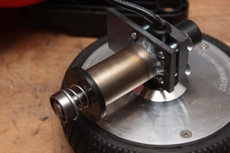
A stainless steel tube sits on the plastic ring (42mm diameter, 5mm thickness).
Inside of that a 8mm rod is inserted though the plastic ring on the one side and through a cylinder on the other side to keep it centered.
A spring is then used to keep the ball bearing from falling out.

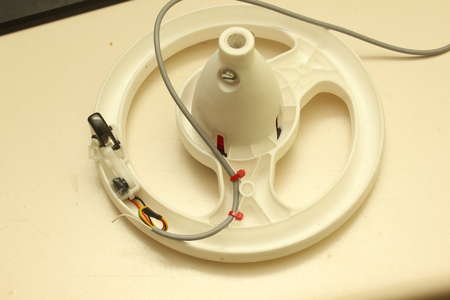
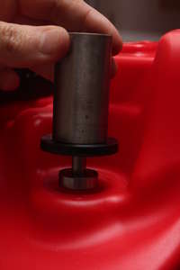
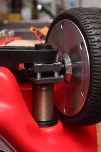
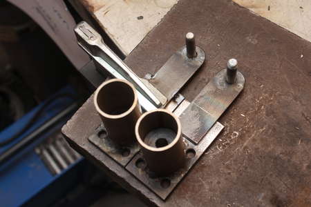
The following pictures show how to attach this part to the Bobby Car.
But how is the wheel attached to the tube? Well ..
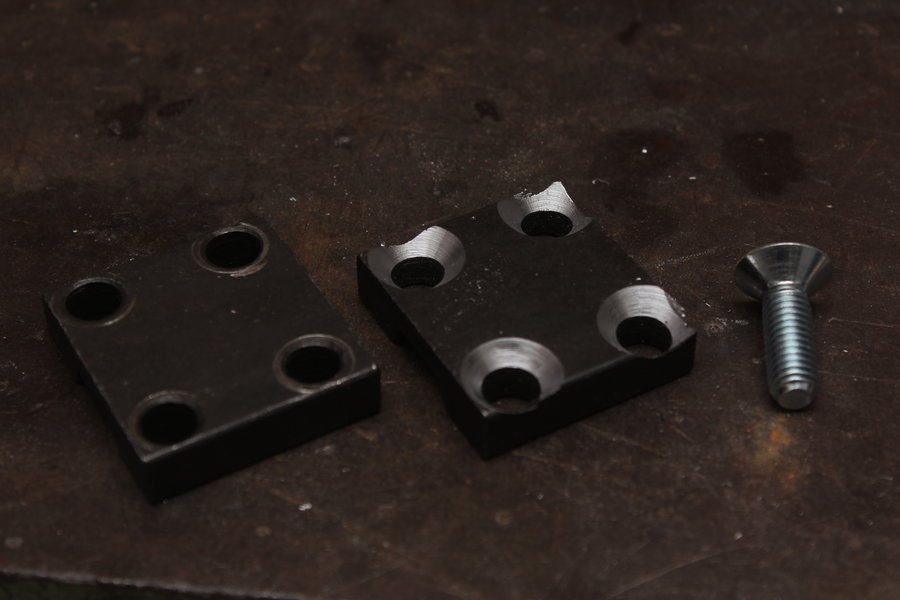
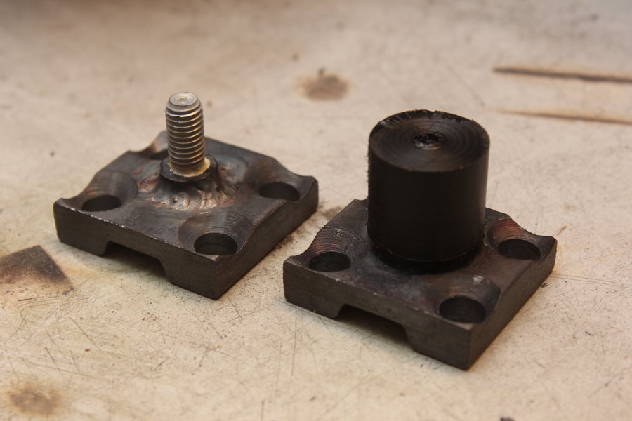
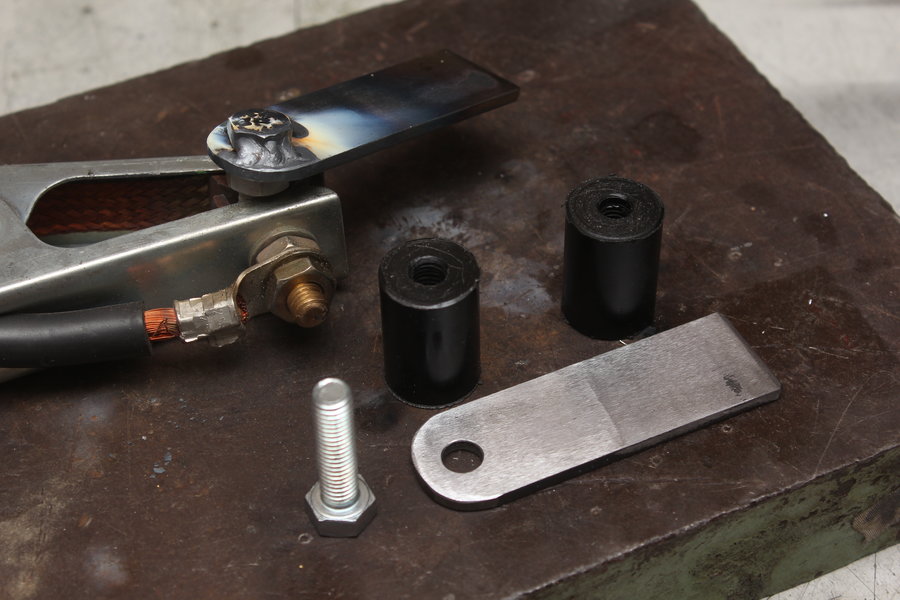
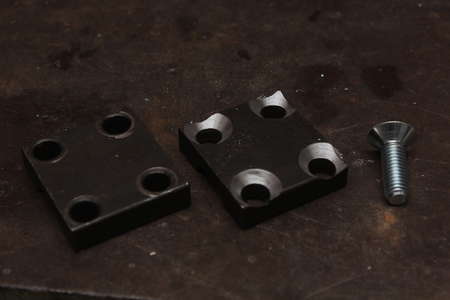
A metal plate is later welded on top of the stainless steel tube through which four holes with M8 thread are drilled and tapped.
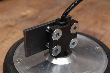
This allows the mounting plates from the Hoverboard to be used to clamp the shaft down, just like I did with the rear wheels earlier.
But as you will see soon I am going to need the space on top of this plate.
For this I bought 25mm long M8 countersunk bolts and made them sit flush with the surface.
The previously mentioned plastic part, which keeps the whole steering mechanism together, sits on top of the steering axles (with the Bobby Car lying on its back).
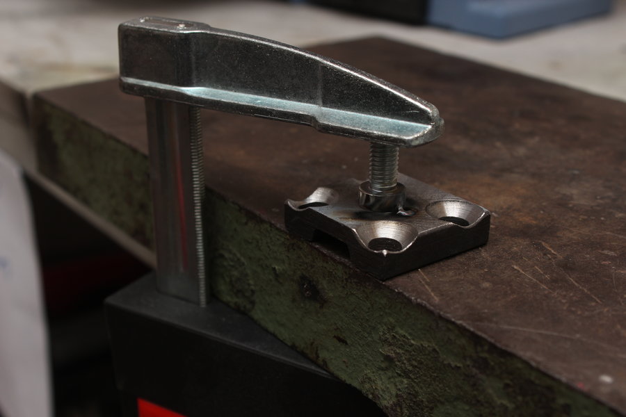
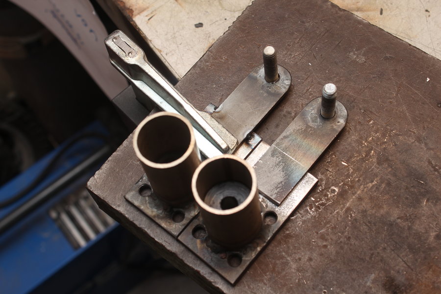
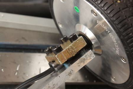
The last missing thing is the one which connects to this part. First I had to find the center of the mounting plate.
The center depends on the position of the screws so I put them in and tried finding the center with a caliper as good as possible.
After setting it up centered on the mill a circle was scratched into the surface. This was done to have a visual aid for placing a bolt and clamping it down.
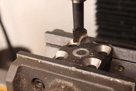
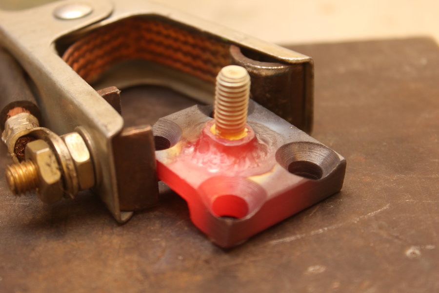
Some Hoverboards use plastic or aluminium mounting plates, this one was made out of steel. This made it easy to weld the bold directly to it.
After that a cylinder turned out of POM material was screwed to serve as the inner part of a slide bearing.


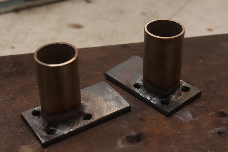
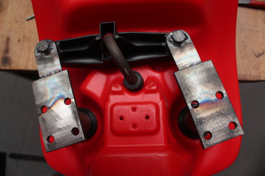
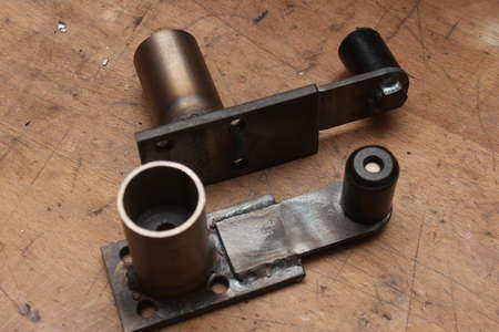
As indicated earlier the steel plate had to be welded to the tube.
After this the other parts like steel rod, POM parts, springs and the ball bearing just needed assembly.


I kept the main concept and dimensions for the steering the same so I could just swap one steering axle out for the new one for testing.
Building the other side was done exactly the same.
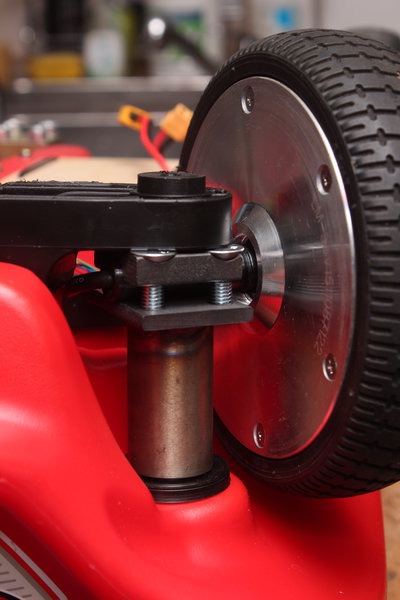
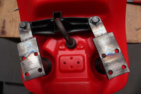
In order to be able to steer again the steering lever was the only thing missing now. For this another POM cylinder is used as a slide bearing attached to a metal plate which is welded to the steering axle, one for each side.
The length were directly taken from the Bobby Car.
And so the steering works again.
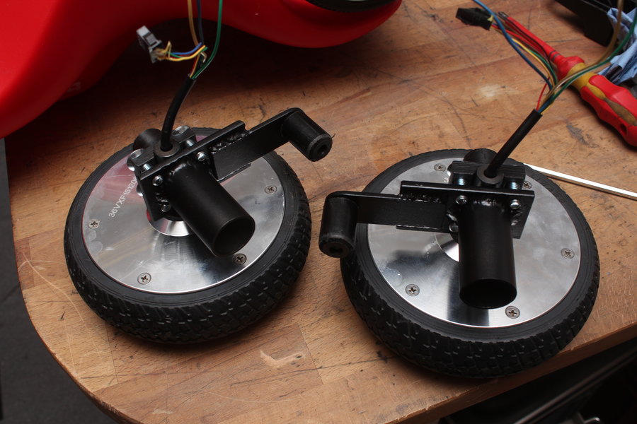
To protect against rust and for the looks a layer of matt black spray paint was applied.
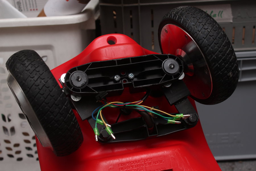
I attached both wheels and put everything back on the Bobby Car.

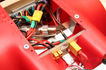
The cabling from the front wheels was routed through the shortest path into the body of the vehicle. This meant drilling two holes to fit the connectors and wires through.
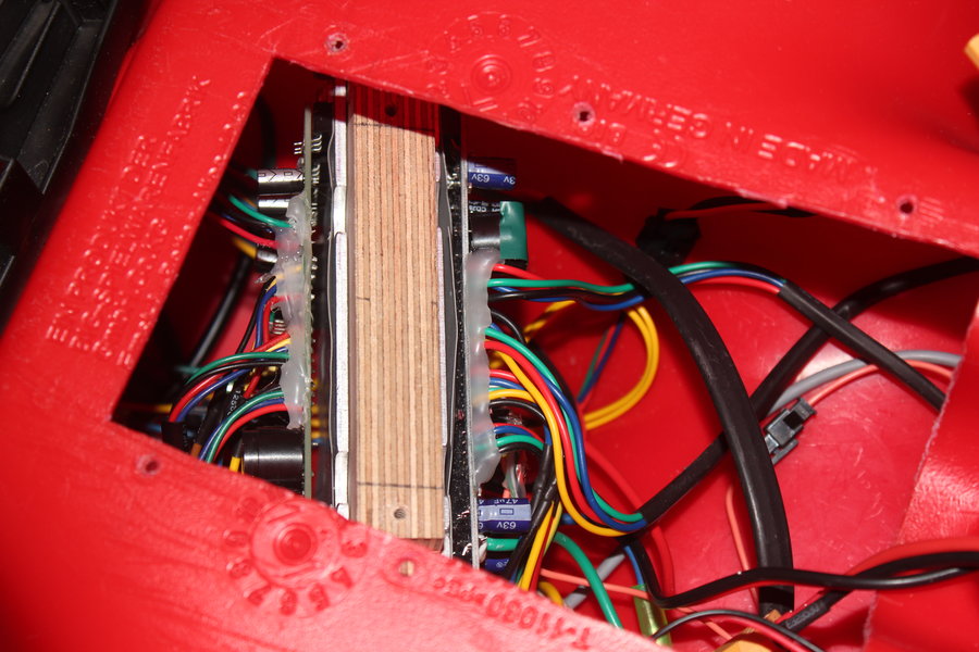
Another Hoverboard mainboard was programmed and then added to the other side of the wooden block where the first one is already attached to.
A Y adapter is used to attach one battery to both mainboards.
Ground and the signal wire from the throttle potentiometer were simply connected to both controllers, whereas 3V3 is only taken from one of the boards.
I wasn't quite sure if the latching circuit where the power buttons are connected to can be wired in parallel. Later I will most likely use optocouplers or relais to turn the controllers on.

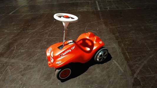
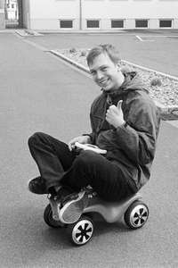
Here a picture taken at EasterHegg 18 in Würzburg:
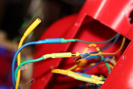
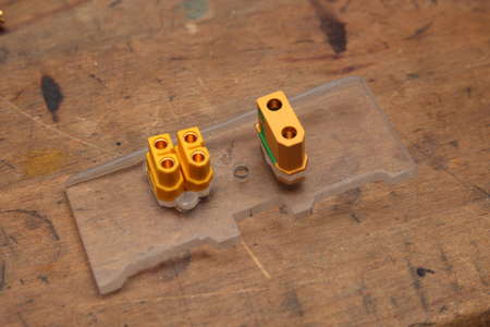
At the last minute, just before leaving Würzburg one of the front wheels quit it's job. Wiggling the wiring made it work again. I assume a bad contact at the connectors of the motor wires, which are honestly speaking very crappy.
To fix that issue I replaced all twelve joints with 4mm gold connectors. I also switched the front wheels for similar looking ones to match the rear wheels and at the same time extended their wires to make assembly easier.
One motor showed itself defective, probably a bad hall sensor. The picture on the right shows the inner workings of such outrunner. Be careful when pulling one apart, strong magnets are strong!
Akku
The 10S2P LiIon battery pack from a hoverboard worked quite well and yielded a long enough driving time.
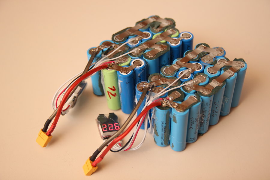
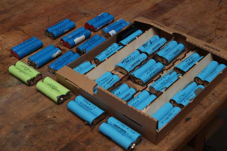
But theres still a bit more room inside the Bobby Car and having a few 18650 cells available from other bad hoverboard batteries, where at least on cell was at 0V, made it possible for me to build a new 12S4P LiIon pack.
To do a bit more pre planning I first measured the 54 cells, which I kept connected as two in parallel. First charging them to 4.1V, then first discharging at 2A, after that further down at 0.5A and writing down their thereby measured capacities and internal resistances.
Three of the 27 2P cells showed a significantly higher resistance. Using the remaining good 24 pairs I was able to plan for a 12S pack.

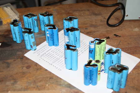
Every cell got an ID, which I put into a spreadsheet together with the corresponding capacity.
By connecting two 2P cell pairs in parallel to 4P the capacities will add together.
In order to have all series connected cells discharge at a similar rate the individual capacities should be as a close match as possible.
Using 24 cells one will find that there are 316234143225 possibilities to wire them up. First I tried bruteforcing the optimal solution by means of a python script. The approximate calculation time of 10 days made myself rethink this approach.
A greedy algorithms proved itself to be much more efficient. First all possible combinations of two were generated and their deviation to the overall mean capacity calculated. Then this list is then sorted in descending order.
After that all possible combinations will still be run through recursively, but they are taken out of the sorted list.
It may not be the best solution to take the pairs with least deviation first, but the most likely optimal solution is found in a few seconds.
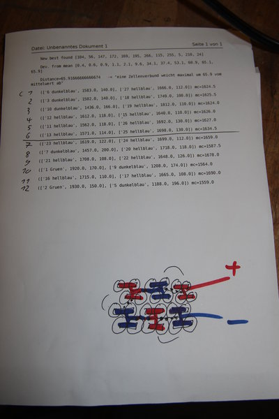
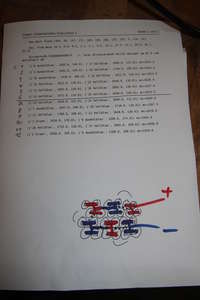
After the algorithm did not give me any better results after a few minutes I stopped the program and got the following configuration:
Pack1
C1: (['6 dunkelblau', 1583.0, 140.0], ['27 hellblau', 1666.0, 112.0]) mc=1624.5
C2: (['3 dunkelblau', 1502.0, 140.0], ['18 hellblau', 1749.0, 100.0]) mc=1625.5
C3: (['10 dunkelblau', 1436.0, 166.0], ['19 hellblau', 1812.0, 110.0]) mc=1624.0
C4: (['12 hellblau', 1612.0, 118.0], ['15 hellblau', 1640.0, 110.0]) mc=1626.0
C5: (['11 hellblau', 1562.0, 118.0], ['26 hellblau', 1692.0, 130.0]) mc=1627.0
C6: (['13 hellblau', 1571.0, 114.0], ['25 hellblau', 1698.0, 130.0]) mc=1634.5
Pack2
C7: (['23 hellblau', 1619.0, 122.0], ['24 hellblau', 1699.0, 112.0]) mc=1659.0
C8: (['7 dunkelblau', 1457.0, 200.0], ['20 hellblau', 1718.0, 118.0]) mc=1587.5
C9: (['21 hellblau', 1708.0, 108.0], ['22 hellblau', 1648.0, 126.0]) mc=1678.0
C10: (['1 Gruen', 1920.0, 170.0], ['9 dunkelblau', 1208.0, 174.0]) mc=1564.0
C11: (['16 hellblau', 1715.0, 110.0], ['17 hellblau', 1665.0, 108.0]) mc=1690.0
C12: (['2 Gruen', 1930.0, 150.0], ['5 dunkelblau', 1188.0, 196.0]) mc=1559.0
As you can probably see I split the 12S battery into two 6S4P batteries.
With this configuration I am able to use my rc lipo charger.
A bigger battery also wouldn't fit through the opening.
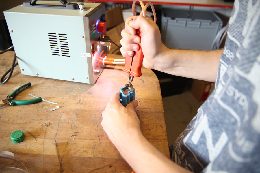
Now the first as 4P connected sets had to be spot-welded in series. To give it more rigidity I used some hotglue first in between the cells.
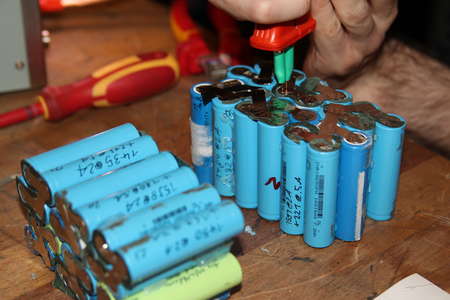
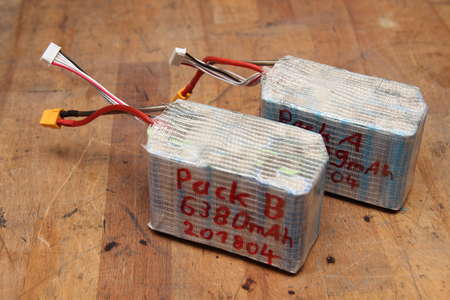
I attached a XT60 and a 7 pin JST-XH connector for balancing. Then a final discharge and charge to check the capacity of the finished batteries.
Pack1/A: 6489mAh (iR=97mOhm)
Pack2/B: 6380mAh (iR=105mOhm)

A bit more brainpower went into the placement of these.
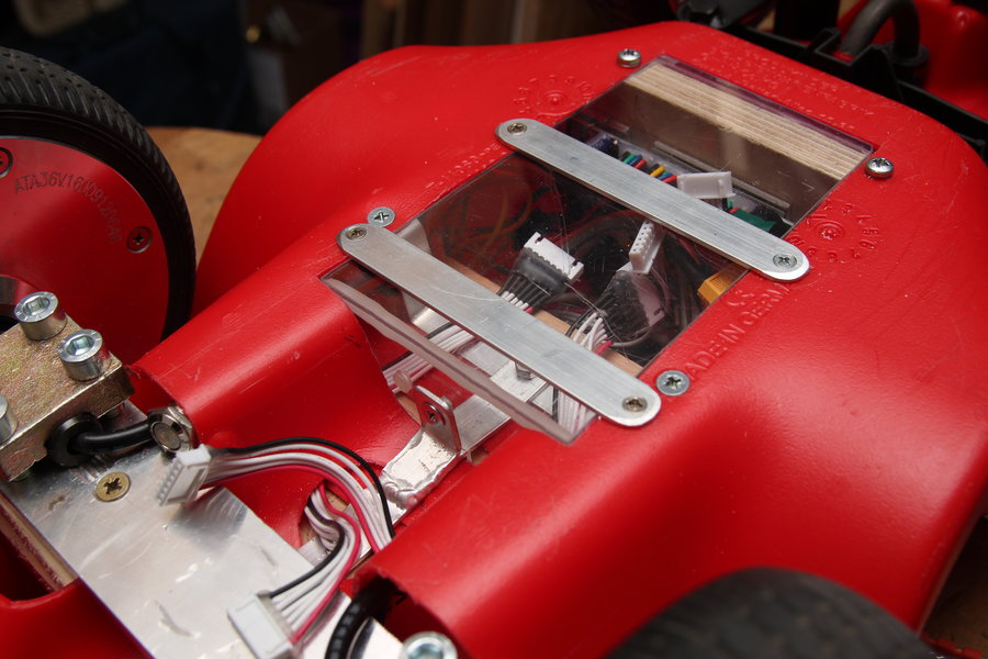
First the protruding plastic piece had to make way. A wooden plate was used to strap the batteries onto with, of course, red velcro strip and then using bent aluminium profiles to screw it to the plastic.
To make it a bit more water resistant I cut a piece of acrylic sheet to close up the hole and also in a 90 degree angle a thicker acrylic plate.
Because the batteries are now kinda inaccessible I wanted to seperate them electrically in order to charge them individually and also to disconnect the main power.
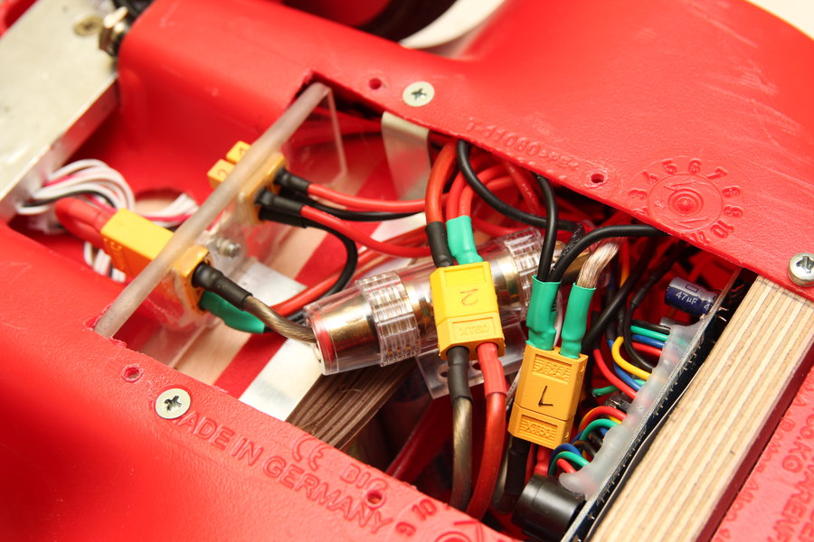
For this two XT60 and a XT90 Antispark socket were fittet into the aforementioned thick acrylic plate.
The XT60 connectors are directly wired to the batteries. The XT90 Antispark connects the batteries in series by means of a simple loop connector.
I also added an AGU fuse and everything is tip top. The highest I was able to measure until now was a peak current of 40A, so a 40A fuse should be fine for now.
When charing both 6S batteries at the same time I really have to make shure to have the XT90 loop disconnected. Otherwise a probably scary bang would be heard when shorting them over a common ground.

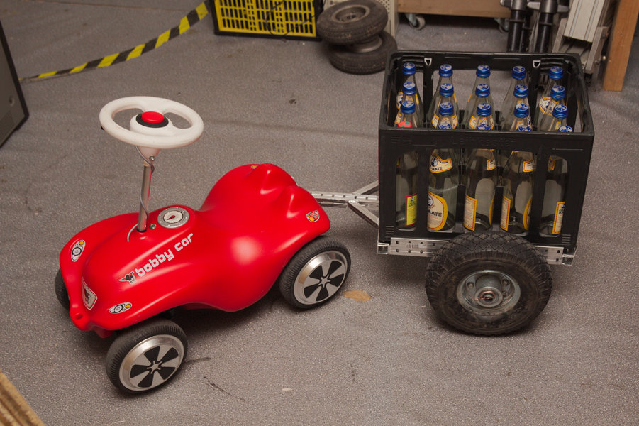
After this I build a small trailer with a standardized size of 400x300 mm for beverage crates. The documentation for that can be found here:
Bobbycar Trailer
Using this trailer I was able to carry a half sized beer crate over 5 km with medium speed and only recharded 2300 mAh afterwards. Using calculus a range of more than 13 km would be possible.

Throttle Lever
The shoulder trigger from the gamepad was really only meant as a quick solution, but it actually worked pretty well.
Nevertheless it was only a movement of 10mm to reach full throttle, which made it difficult to accelerate from a standstill.
I wasn't really able to find another simple solution other than the one I was thinking about from the beginning.
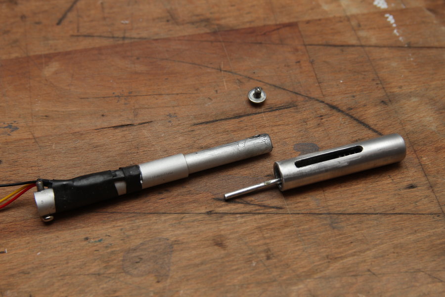
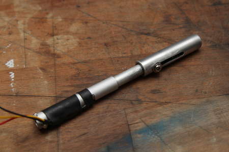
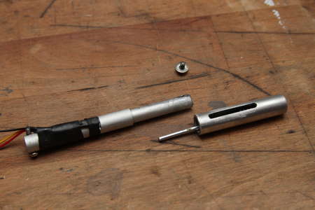
Here instead of a potentiometer a 2cm long rod magnet is moved in front of a hall sensor, which then outputs an analog voltage depending on the magnetic field at that point.
The magnet is placed inside the aluminium tubes and pressed to one end with a spring. By pressing the lever an aluminium rod pushes the magnet in the direction of the spring.
The hall sensor is epoxyed in place together with a heatshrink tube.
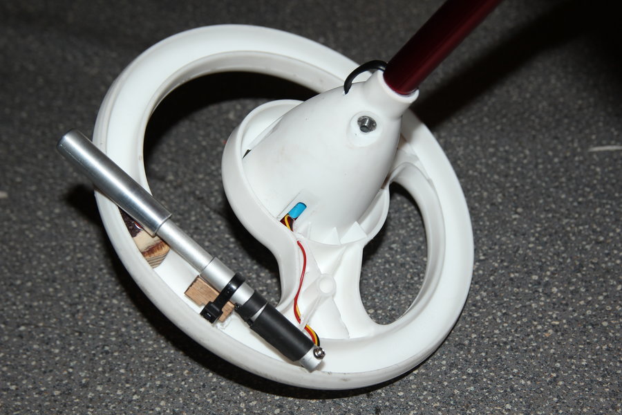
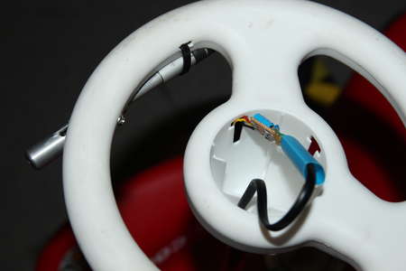
I also used this opportunity to replace the wiring from the steering wheel to the controller.
This time it is a bit smaller and can be routed between the aluminium tube and the steering rod.
First I tried building a throttle level in a rounded shape to match the steering wheels shape. This didn't work out and the front part hast to stick out a bit.
On the underside a zip tie mounts the newly build throttle lever.
The screw going through the slot in the moving part of the lever was exchanged for a longer one to also go through a wooden block inside the inner part of the steering wheel.
Using a few washers I was able to space the lever away from the pastic so everything can slide without dragging or sticking.
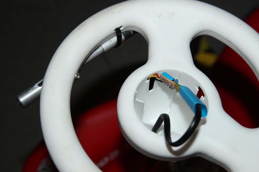
Also I had to add a 2.2µF capacitor parallel to ground and the signal output of the hall sensor in order to filter out the bit of judder i was experiencing.
A 100nF capacitor across gnd and 3.3V just before the sensor also helps a bit smoothing out the voltage supply. It's not the best solution but it worked for me.
This small perfboard was then hidden underneath the horn.
Using this throttle lever is it now 2cm of travel from zero to full throttle. The voltage curve is not quite linear with the distance pushed and is a bit steeper at the end. Fortunately this helps when starting.

 Continue reading: Controller
 Bobbycarbau